PORTA SCORREVOLE AUTOMATICA - Manuale d'uso e manutenzione per l'utilizzatore - AUTOMATIC SLIDING DOOR - MIV Insulating ...
←
→
Trascrizione del contenuto della pagina
Se il tuo browser non visualizza correttamente la pagina, ti preghiamo di leggere il contenuto della pagina quaggiù
PORTA SCORREVOLE AUTOMATICA

             AUTOMATIC SLIDING DOOR

                                         ITA-ENG

Manuale d’uso e manutenzione per l’utilizzatore

            Use and Maintenance Manual
                        -1-               Edizione 04/2019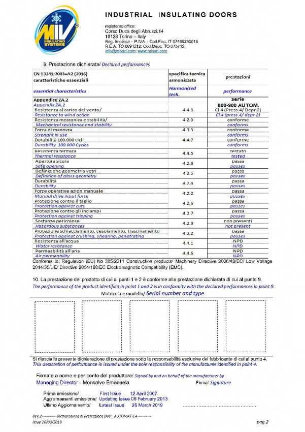
PREFAZIONE / FOREWORD

       Nel ringraziarVi per aver scelto la nostra porta scorrevole automatica mod.’’900'’,
       Vi informiamo che questo modello è conforme alle norme generali espresse nella
              Regulation (EU) No 305/2011 Construction products
                        2006/42/EC Machinery Directive
                            2014/35/UE Low Voltage
          Directive 2004/108/EC Electromagnetic Compatibility (EMC).
             Al fine di garantire un perfetto funzionamento e ottenere le migliori
          prestazioni possibili è opportuno, prima dell’utilizzo, leggere attentamente
          questo manuale. Ricordiamo che la porta automatica deve essere montata
                            da personale addestrato e competente
                 I dati forniti in questo manuale sono forniti a titolo indicativo.
        La ditta ‘’ MIV INSULATING SYSTEMS ‘’ S.r.l. potrà apportare in qualunque
     momento modifiche al modello descritto per ragioni di natura tecnica o commerciale.

                       Per ogni controversia è competente il foro di Torino

          Per qualsiasi comunicazione con il costruttore od il fornitore citare sempre i
                    dati riportati nella targhetta di identificazione della porta

Il manuale deve accompagnare la porta scorrevole in caso di rivendita

               Thank you very much for choosing our ‘’900'’ automatic sliding door;
  we are pleased to inform you that this product complies with the general standards states in the
                  Regulation (EU) No 305/2011 Construction products
                            2006/42/EC Machinery Directive
                                2014/35/UE Low Voltage
              Directive 2004/108/EC Electromagnetic Compatibility (EMC).
                                 In order to ensure its perfect operation,
                             and to achieve the best performances possible,
            it is advisable to carefully read the following instruction manual before its use

           The data provided in this manual should be purely considered as an indication.
                      At any time and for any technical or commercial reason,
      the company ‘’MIV INSULATING SYSTEMS S.r.l.’’ will be able to add any modification to
                                        the described model.

                      Any controversy will be settled by the Court of Turin (Italy)

 In any communication with the manufacturer or the supplier, please always specify the data printed
                                  on the door identification tag.

if the automatic sliding door is resold, this manual should accompany it

     Via Albert Einstein, 23
  10051 AVIGLIANA (TO - Italy)
     Tel +39 011 93 69 487
     Fax +39 011 93 69 488
     http:// www.mivsrl.com
    e-mail : info@mivsrl.com

                                                 -2-
INDICE GENERALE / TABLE OF CONTENTS

Pag. 4   - Dichiarazione di prestazione DoP / Declaration of performance Dop

Pag. 5   - Caratteristiche / Main features

Pag.-6-7   - Istruzioni per l’installazione / Installation instructions

Pag. 8   - Istruzioni di utilizzo / Use instructions

Pag. 9   - Istruzioni di funzionamento / Operation instructions

Pag.10 -   Dispositivi di sicurezza / Safety features

Pag.11 -   Manutenzione / Maintenance

Pag.12 -   Avvertenze d’uso / Warning of use

Pag.13 -   Anomalie di funzionamento, incidenti / Failures and faults

Pag.14 -   Anomalie di funzionamento, incidenti / Failures and faults

Pag.15 -   Incidenti / faults

Pag.16-18 -    Schemi montaggio in cantiere / Assembly at building

Pag.19 -   Schema montaggio copribinario / Diagram cover assembly

Pag.20 -   Regolazione micro finecorsa / Limit stop regular

Pag.21 -   Dispositivo di trascinamento / Device drag blade

Pag.22 -   Ingombri porta / Automatic doors dimensions

Pag.23 -   Impianto elettrico / Electric components

Pag.24 -   Componenti / Components

Pag.25 -   Schema fotocellule / Photoelectric cells

Pag.26-31 -    Schemi eletrici / Diagram electric

                                    -3-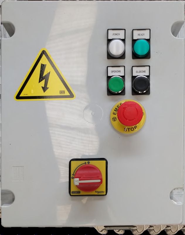
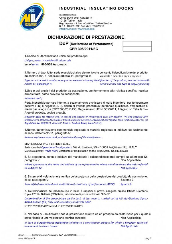
DICHIARAZIONE DI PRESTAZIONE
DECLARATION OF PERFORMANCE

             -4-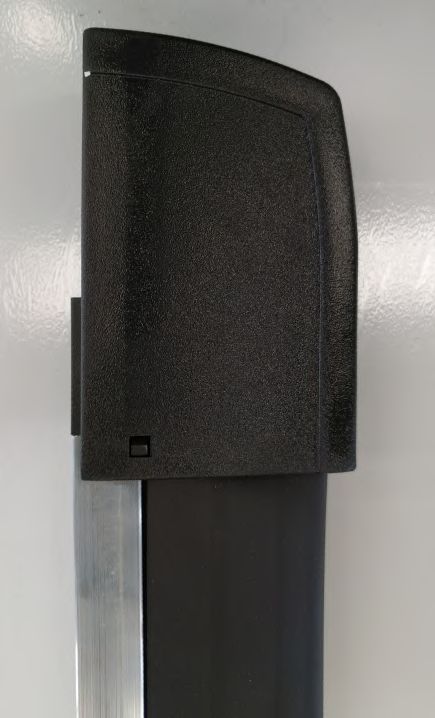
CARATTERISTICHE
                               MAIN FEATURES

ALIMENTAZIONE / POWER SUPPLY

     Mono fase / Single phase 230 Volt +/- 10 % 50 Hz +/- 1 %

AZIONAMENTO / DRIVING GEAR

     Motoriduttore / Gearmotor :

     - Rapporto riduzione / Redution ratio 1 : 24.5
     - Potenza installata / Installed power Kw 0.37

     Trasmissione / Drive :

     - Catena a rulli / Roller chain 5/8 x 3/8

APPARECCHIATURA ELETTRICA / ELECTRIC EQUIPMENT

     Cassetta comandi in materiale plastico autoestinguente a tenuta stagna IP56
     IP56 sealed self-extinguishing plastic control box, lockable by tool

     Schemi elettrici / Electric diagrams : dis 9835MV 1/2/3/4/5/6/7

IMPIANTO ELETTRICO / ELECTRIC SYSTEM

    Deve essere realizzato in conformità alla norma / The electric system must be
    compliant to the standard

    EN 60204-1

                                           -5-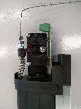
ISTRUZIONI PER L’INSTALLAZIONE
                          INSTALLATION INSTRUCTION

INSTALLAZIONE MECCANICA / MECHANICAL COMPONENTS INSTALLATION

            Effettuare il montaggio della porta scorrevole automatica secondo la sequenza
                            di operazioni indicate sui nostri schemi da pag.16

Assemble the automatic sliding door according to sequence of steps described on our diagram pag.16

   INSTALLAZIONE ELETTRICA / ELECTRIC COMPONENTS INSTALLATION
                          1- Posizionare e fissare alla parete la cassetta elettrica
                               Place and secure the electric box to the wall.

                2- Posizionare e fissare le fotocellule come indicato nello schema pag 25
                   Place and secure the posts carrying the photoelectric cells pag.25

       3- Eseguire i collegamenti elettrici secondo quanto indicato negli schemi elettrici pag.26
      Perform electric connections according to the instructions provided on the diagrams pag.26

4- Eseguire allacciamento al quadro di comando con tensione di alimentazione 230 V monofase + terra
                            a monte dell’interruttore magnetotermico (QS1)
               Connect the electric box to the 230 V single phase power supply + ground,
               in an upstream position with respect to the magnetothermic switch (Qs1).

    5- Verificare il senso di rotazione del motore con il battente posizionato, per questa operazione,
                                           a metà della corsa totale.
                     Make sure the motor rotates in the correct direction, when the door
                                   is activated along half of its total stroke.

               6- Se la porta si muove nella direzione opposta (chiusura anziché apertura),
         attivare l'emergenza per fermare la corsa e invertire il collegamento elettrico delle fasi.
                  If the door moves in the opposite direction (closing instead of opening),
            activate emergency to stop the run and reverse connection electric of the phases.

7- Verificare la funzionalità dei dispositivi di sicurezza installati e dei fine corsa di apertura e di chiusura
                       (che devono provocare l'arresto immediato del motore elettrico).
     Make sure that the safety devices installed, as well as the opening and closing stroke stops,
                       work correctly (they should immediately stop the electric motor)

                                  NOTA IMPORTANTE/IMPORTANT NOTE

Tutti gli interventi elettrici devono essere eseguiti da personale qualificato in conformità con la norma
                               EN 50110-1 (CEI 11-27 -IV edizione e CEI 11-48)
       All the electrical interventions must be carried out by "skilled personnel", in accordance with the
                    EN 50110-1 Technical Standard (CEI 11-27 - IV ^ edition and CEI 11-48)
                                       for 'operation of electrical installations'

                                                     -6-
ISTRUZIONI PER L’INSTALLAZIONE
INSTALLATION INSTRUCTION
Una volta completati i collegamenti elettrici:
Once the electrical connections have been completed :
! ATTENZIONE SE LA LUCE VERDE È ACCESA (PANNELLO DI CONTROLLO ESTERNO),
INDICA TUTTI I DISPOSITIVI DI SICUREZZA, COME FOTOCELLULE,
BORDO SENSIBILE, CONNESSI E ATTIVI
! PAY ATTENTION IF GREEN LIGHT IS ON (EXTERNAL CONTROL PANEL),
INDICATES ALL THE SAFETY DEVICES, AS PHOTOCELLS,
SENSITIVE EDGE, CONNECTED AND ACTIVE
! ATTENZIONE SE LA LUCE VERDE NON È ACCESA (PANNELLO DI CONTROLLO ESTERNO),
INDICA TUTTI I DISPOSITIVI DI SICUREZZA, COME FOTOCELLULE,
BORDO SENSIBILE, NON SONO ATTIVI
! PAY ATTENTION IF GREEN LIGHT IS OFF (EXTERNAL CONTROL PANEL),
INDICATES ALL THE SAFETY DEVICES, AS PHOTOCELLS,
SENSITIVE EDGE, THEY ARE NOT CONNECTED.
8- Verificare la funzionalità dei dispositivi di sicurezza installati e dei fine corsa di apertura e di chiusura
(che devono provocare l'arresto immediato del motore elettrico).
Make sure that the safety devices installed, as well as the opening and closing stroke stops,
work correctly (they should immediately stop the electric motor).
9- Regolare la posizione dei 2 microinterruttori (apertura e chiusura) in modo che:
all'apertura, la porta si ferma al microinterruttore senza colpire il bumper;
in chiusura, la porta termina la corsa all'interno delle curve, senza oltrepassarle
(rischio di ribaltamento e rottura del gancio sul telaio).
Adjust the position of the 2 microswitches (opening and closing)so that:
at the opening, the door stops at the microswitch without getting to hit on the bumper;
in closing, the door ends the run inside the curves, not going beyond them
(overturning risk and hook breakage on the frame)
10- Regolare il temporizzatore (TC) di richiusura automatica del battente con il tempo desiderato.
(TC) Time relay for adjusting the desired period of automatic closing
(’stop’ time in opening position)
11- Verificare il corretto collegamento a terra del motore elettrico e di tutte le parti metalliche (telaio e binari)
Make sure the electric motor ground cable connection is correct, and inspect fastening of
all the metal parts (frame and tracks).
Effettuare un ciclo completo di controllo di apertura e chiusura
Perform a complete opening and closing cycle as a test.
NOTA IMPORTANTE/IMPORTANT NOTE
Tutti gli interventi elettrici devono essere eseguiti da personale qualificato in conformità con la norma
EN 50110-1 (CEI 11-27 -IV edizione e CEI 11-48)
All the electrical interventions must be carried out by "skilled personnel", in accordance with the
EN 50110-1 Technical Standard (CEI 11-27 - IV ^ edition and CEI 11-48)
for 'operation of electrical installations'
-7-ISTRUZIONE PER L’USO
INSTRUCTION FOR USE
ISTRUZIONE PER L’ USO
INSTRUCTION FOR USE
Accensione (Luce bianca)
Power On ( light white )
DANGER
VOLTAGE Sicurezze attive (luce verde)
Ready Safety On (green ligth)
Apertura porta (pulsante verde)
Door opening (green button)
Chiusura porta (Pulsante nero)
220 VOLT
Door closing ( black button )
Pulsante rosso Emergenza
Emercency stop red push button
Interruttore sezionatore
Switch disconnector
DISPOSITIVI DI SICUREZZA
SAFETY DEVICE
Costa sensibile (sicurezza di contatto)
Sensitive edge (contact safety device)
Fotocellule (quando prevista)
Photoelectric cells (if installed)
Lampeggiante (giallo) messa in funzione
Door leaf operation warning flasher
MANUTENZIONE
MAINTENANCE
Pulizia periodica
Routine cleaning
Controllo parte meccanica
Mechanical components inspection
Controllo parte elettrica
Electric components inspection
NOTA IMPORTANTE/IMPORTANT NOTE
Tutti gli interventi elettrici devono essere eseguiti da personale qualificato in conformità con la norma
EN 50110-1 (CEI 11-27 -IV edizione e CEI 11-48)
All the electrical interventions must be carried out by "skilled personnel", in accordance with the
EN 50110-1 Technical Standard (CEI 11-27 - IV ^ edition and CEI 11-48)
for 'operation of electrical installations'
-8-ISTRUZIONI DI FUNZIONAMENTO COMANDI
OPERATION INSTRUCTIONS CONTROLS
APERTURA / DOOR OPENING
L’ apertura del battente verrà comandata tramite pulsante ‘’verde’’ (SB3)
situato sul quadro di comando oppure in opzione tramite interruttore ‘’TIR’’ a funicella
appeso al soffitto o tramite ‘’radiocomando’’ (RD).
Il battente si arresterà al termine della corsa di apertura a seguito intervento
del microinterruttore di fine corsa (SA).
Qualora l’apertura venga interrotta a causa dell’azionamento di ARRESTO
con il pulsante a fungo colore ‘’rosso’’ (SB1) situato sulla cassetta elettrica,
il ciclo potrà essere portato a termine ripristinando lo stesso
ed agendo sull’apposito comando: pulsante ‘’verde’’ (SB3) situato sul quadro di comando
oppure tramite interruttore ‘’TIR’’ a funicella o tramite ‘’radiocomando’’ (RD)
/
The door leaf will open when the ‘’green’’ button in the control box is press (SB3),
or when the ‘’TIR’’ string-operated switch installed in the ceiling is pulled
o by means of a ‘’remote-control’’ (RD)
The door leaf will stop when it reaches its stroke end, following the activation of stroke-stop
micro-switch(SA).
If the opening procedure is interrupted due to the activation of the red mushroom-shaped STOP button(SB1)
located in the electric box, the cycle could be completed by resetting it and by pressing the suitable control:
the ‘’ green’’ button (SB3) in the control box, or by pulling the ‘’TIR’’ string-operated switch
or by using the ‘’remote-control’’ (RD)
CHIUSURA / DOOR CLOSING
La chiusura del battente avverrà automaticamente dopo un periodo regolato
da un temporizzatore (TC) da 1 a 30 secondi. L’arresto del battente al termine
della corsa di chiusura avverrà per intervento del microinterruttore di fine corsa (SC).
Il battente assumerà la posizione ‘’PORTA CHIUSA’’ tramite la caduta delle ruote di scorrimento
nelle curve del binario e, in questa posizione, le guarnizioni assicurano la tenuta prevista.
La chiusura del battente potrà essere azionata manualmente, tramite il pulsante ‘’nero’’ (SB4)
qualora si volesse anticipare la chiusura della porta senza attendere la temporizzazione;
sempre tramite pulsante ‘’nero’’ (SB4) potrà essere completatal’operazione di chiusura,
con il battente fermo in una posizione intermedia, dopo l’arresto dello stesso battente a causa di:
- intervento di un dispositivo di sicurezza
The door leaf will close automatically once the time set in the timer(TC)
has elapsed (usually after 1 to 30 second). At the end of its stroke, the door leaf will be stopped by the
activationof a stroke-stop micro-switch (SC). The door will stay in the ‘’CLOSED DOOR’’ mode by means of
the insert installed on the sliding track and, when the door is in this position , rubber seals ensure the
expected tightness. The door leaf closing procedure can be performed manually, by pressing the ‘’black’’
button(SB4) if the user wishes to anticipate the door closing without waiting for the timer input; after the
cause of the stop has been removed or resolved, through the ‘’black’’ button (SB4) the user will also be able to
complete the closing procedure, in case the door leaf stops half
- way through its course due to one of the following reasons
- activation of a safety device
ARRESTO / STOP
L’arresto tramite pulsante a fungo colore ‘’rosso’’ (SB1) situato sulla cassetta elettrica provoca
l’interruzione di corrente sui circuiti di comando
/
The door operation can be stopped by pressing the red mushroom-shaped button(SB1)
located in the electric box; its activation cuts out the power supply to the control circuits.
NOTA IMPORTANTE/IMPORTANT NOTE
Tutti gli interventi elettrici devono essere eseguiti da personale qualificato in conformità con la norma
EN 50110-1 (CEI 11-27 -IV edizione e CEI 11-48)
All the electrical interventions must be carried out by "skilled personnel", in accordance with the
EN 50110-1 Technical Standard (CEI 11-27 - IV ^ edition and CEI 11-48)
for 'operation of electrical installations'
-9-ISTRUZIONI DI FUNZIONAMENTO COMANDI
OPERATION INSTRUCTIONS CONTROLS
COSTA SENSIBILE
SENSITIVE EDGE
Montata sul bordo del battente "lato chiusura".
In caso di interferenza con un ostacolo, in fase di chiusura del battente,
si registrerà l'intervento di un contatto elettrico, il battente si arresterà
e si rimetterà in movimento in direzione opposta, senso di apertura.
The sensitive edge is located on the edge of the door leaf "closing side",
along a 2 meters height from the floor.
In case of interference with an obstacle, during the door leaf closing phase, an electric contact will be activated,
and the door leaf will immediately stop its travel and move backward along the track in the opening direction
Durante l’uso l’uscita del contato e normalmente chiuso NC
(se la costa sensibile lavora l’uscita del contatto e normalmente aperto NO)
During the use the output contact is NC.
(If the safety edge works
the output is NO contac).
FOTOCELLULA (se installate) /
PHOTOELECTRIC CELLS (if installed)
Dovranno essere montate all'esterno ed all'interno (non previste per locali a
bassa temperatura) della cella frigorifera in corrispondenza dell'apertura della porta.
Il movimento del battente in fase di chiusura sarà interrotto in caso
di interferenza con un ostacolo, si registrerà l'intervento di un contatto elettrico,
il battente si arresterà e si rimetterà in movimento in direzione opposta, senso di apertura.
/They will have to be installed both outside and inside (not suitable to low temperature rooms)
the refrigerating room, by the door opening, at a distance of 0,10 metres from the moving door leaf.
The door leaf movement during the closing phase will be interrupted in case of interference with an obstacle;
an electric contact will be activated, the door leaf will stop its course and move backward along the track
in the opening direction.
LAMPEGGIATORI MOVIMENTO BATTENTE
DOOR OPERATION WARNING FLASHERS
Dovranno essere sistemati all'esterno ed all'interno della cella frigorifera.
Di colore arancione (HL1), metteranno in funzione automaticamente quando il battente inizierà il movimento
"comandato elettricamente" sia in fase di apertura sia che in caso di chiusura.
/Warning flashers will have to be installed both outside and inside the refrigerating room.
They are orange in colour (HL1), and they will be automatically activated during the door
leaf "electrically-controlled" movement, both during closing and opening operations.
NOTA IMPORTANTE/IMPORTANT NOTE
Tutti gli interventi elettrici devono essere eseguiti da personale qualificato in conformità con la norma
EN 50110-1 (CEI 11-27 -IV edizione e CEI 11-48)
All the electrical interventions must be carried out by "skilled personnel", in accordance with the
EN 50110-1 Technical Standard (CEI 11-27 - IV ^ edition and CEI 11-48)
for 'operation of electrical installations'
- 10 -MANUTENZIONE
MAINTENANCE
ATTENZIONE: non eseguire nessuna operazione di manutenzione con porta in movimento
o con porta ferma e corrente inserita.
WARNING: do not carry out any maintenance operation with the door moving
o with door stopped and current inserted.
PULIZIA PERIODICA / ROUTINE CLEAING
Eseguire periodicamente (almeno una volta al mese) una accurata pulizia
di tutte le parti ove avviene lo scorrimento della porta (binario superiore e
guida posteriore) e la chiusura a tenuta del battente (telaio e guarnizioni).
/
Perform on a regular basis (at least once a month) a thorough cleaning of all the door
components where the sliding movement takes place (upper track and rear track)
and on the tight side of the door leaf (frame and seals).
CONTROLLO PARTE MECCANICA / MECHANICAL COMPONENTS INSPECTION
Eseguire periodicamente (almeno una volta al mese) i controlli relativi a:
-funzionamento organi di trasmissione
-tensione catena (o cinghia)
-attacco catena (o cinghia)
-ruote di scorrimento su binario superiore
-registro su guida posteriore
-guarnizione di tenuta in posizione aperta e chiusa
-funzionamento maniglie esterna ed interna di azionamento manuale
-lubrificazione catena di trasmissione
-lubrificazione (con grasso) del binario di scorrimento e della guida posteriore
/
Check on a regular basis (at least once a month):
-operation of transmission gears
-chain tensioning (or belt)
-chain attachment (or belt)
-sliding wheels on the upper track
-adjuster on the rear track
-rubber seal in opening and closing conditions
-operation of external and internal operation handles
-transmission chain lubrication
-sliding track and rear track lubrication (with grease)
CONTROLLO PARTE ELETTRICA / ELECTRIC COMPONENTS INSPECTION
Eseguire periodicamente (almeno una volta ogni 6 mesi) i controlli relativi a:
-revisionare contatti relè di azionamento
-rimozione eventuali ossidazioni o incrostazioni all'interno della cassetta elettrica
-tenuta stagna della cassetta elettrica
-efficienza dispositivi di sicurezza installati (consigliato una volta al mese)
/
Check on a regular basis (at least once every 6 months):
-overhaul activation relays contacts
-remove any oxydation or deposits inside the electric box
-electric box tightness
-efficiency of the installed safety devices (recommended once a month)
NOTA IMPORTANTE/IMPORTANT NOTE
Tutti gli interventi elettrici devono essere eseguiti da personale qualificato in conformità con la norma
EN 50110-1 (CEI 11-27 -IV edizione e CEI 11-48)
All the electrical interventions must be carried out by "skilled personnel", in accordance with the
EN 50110-1 Technical Standard (CEI 11-27 - IV ^ edition and CEI 11-48)
for 'operation of electrical installations'
- 11 -AVVERTENZE D’USO
WARNINGS OF USE
AVVERTENZE D’USO / -
-La costa elettromeccanica è posizionata sul bordo primario del battente.
Non avvicinarsi alla porta quando questa sta effettuando il movimento di chiusura
ed è prossima al contatto con la torretta fissata a pavimento.
-Non inserire le mani per effettuare la manutenzione nella zona delimitata
dal carter riparo motore e cinematismo prima di avere staccato la corrente di alimentazione.
-Non aprire la porta durante la sua fase di chiusura urtando volontariamente la costa sensibile:
è un organo di sicurezza.
-Lasciare sempre libera l'area di movimentazione della porta: devono essere sempre garantiti spazi di 50 cm
minimo dal bordo primario quando la porta è chiusa e 50cm minimo dal bordo secondario quando la porta è aperta.
-Il personale che userà la porta dovrà essere adeguatamente
istruito sulle caratteristiche della porta automatica e i rischi connessi ad un uso non corretto.
WARNINGS OF USE
-The electromechanical edge is positioned on the primary edge of the door leaf.
Do not approach the door when it is closing.
-Do not insert your hands to perform maintenance in the demarcated area
from the engine guard cover and mechanism before disconnecting the power supply.
-Do not open the door during its closing phase voluntarily bumping the sensitive coast:
it is a security organ.
-Always leave the door movement area free: 50 cm spaces must always be guaranteed
minimum from the primary edge when the door is closed and 50cm
minimum from the secondary edge when the door is open.
-The staff who will use the door must be properly
educated on the characteristics of the automatic door and the risks connected to incorrect
NOTA IMPORTANTE/IMPORTANT NOTE
Tutti gli interventi elettrici devono essere eseguiti da personale qualificato in conformità con la norma
EN 50110-1 (CEI 11-27 -IV edizione e CEI 11-48)
All the electrical interventions must be carried out by "skilled personnel", in accordance with the
EN 50110-1 Technical Standard (CEI 11-27 - IV ^ edition and CEI 11-48)
for 'operation of electrical installations'
- 12 -ANOMALIE DI FUNZIONAMENTO - INCIDENTI
FAILURES - FAULTS
1) Rottura o sganciamento catena di trasmissione
1) Breaking or release of the transmission chain
Il battente si ferma, il motore si arresta a seguito dell'intervento del temporizzatore di sicurezza (TL) tempo lavoro.
Togliere tensione all'impianto azionando l'interruttore generale (QS1) posizionato sulla cassetta elettrica.
Effettuare la riparazione o sostituzione e ripristinare le condizioni di lavoro.
The door leaf stops, and the motor stops following the activation of the safety timer (TL) set on working time.
Disconnect power supply to the installation by acting on the main switch (QS1) located in the electric box.
Repair or replace, and reset the door to working conditions.
2) Rottura o scarrucolamento registro dalla guida posteriore.
2) Adjuster breaking or fleeting from the rear track.
Il battente si ferma o continua corsa fuori guida, il motore si arresta a seguito dell'intervento
del temporizzatore di sicurezza (TL) tempo lavoro.
Togliere tensione all'impianto azionando l'interruttore generale (QS1) posizionato sulla cassetta elettrica.
Effettuare la riparazione o sostituzione e ripristinare le condizioni di lavoro.
/The door leaf stops or continues its course off the tracks, and the motor stops following
the activation of the safety timer (TL) set on working time.
Disconnect power supply to the installation by acting on the main switch (QS1) located in the electric box.
Repair or replace, and reset the door to working conditions.
3) If the door no stopping to the contact limit stop (opening / closing)
Disconnettere l’alimentazione agendo sull’interruttore rosso ARRESTO DI EMERGENZA
Disconnect power supply by acting switch red ‘EMERGENCY STOP’
Disconnettere l'alimentazione all'impianto agendo sull'interruttore principale (QS1) situato nella scatola elettrica
Disconnect power supply to the installation by acting on the main switch (QS1) located in the electric box.
Riparare o sostituire e ripristinare la porta alle condizioni di lavoro
Repair or replace, and reset the door to working conditions
NOTA IMPORTANTE/IMPORTANT NOTE
Tutti gli interventi elettrici devono essere eseguiti da personale qualificato in conformità con la norma
EN 50110-1 (CEI 11-27 -IV edizione e CEI 11-48)
All the electrical interventions must be carried out by "skilled personnel", in accordance with the
EN 50110-1 Technical Standard (CEI 11-27 - IV ^ edition and CEI 11-48)
for 'operation of electrical installations'
- 13 -ANOMALIE DI FUNZIONAMENTO - INCIDENTI
FAILURES - FAULTS
In caso di non funzionamento , eseguire le seguenti operazioni:
In case of failed operation, perform the following checks:
- controllo tensione nella linea
- verifica fusibili di protezione (FV1 - FV2)
- verifica funzionamento pulsante di "ARRESTO" (SB1)
- verifica corretto funzionamento del dispositivo inversione fasi
- check line voltage
- check safety fuses (FU1 - FU2)
- check "STOP" button operation (SB1)
- check correct operation of the phase inverter
Oltre alle operazioni indicate precedentemente:
Besides the previously mentioned operations:
1) Se la porta non si apre o si è fermata in fase d'apertura
If the door does not open or stops along its course during the opening phase
- Verificare che non sia intervenuto il fine corsa di apertura (SA)
Make sure the opening stroke stop has not been activated (SA)
2) Se la porta non si chiude o si è fermata in fase di chiusura
If the door does not open or stops along its course during the closing phase
- Verificare che non sia intervenuto il fine corsa di chiusura (SC)
- Verificare che un corpo estraneo non abbia azionato costa sensibile sul bordo del battente
- Make sure the closing stroke stop has not been activated (SC)
- Make sure a foreign entity has not activated the sensitive edge along the door leaf edge
3) Se la porta dopo la fase d'apertura non si richiude
If the door, following its opening, does not close
- Verificare i dispositivi di sicurezza: la connessione elettrica della fotocellula e del bordo sensibile
(Verificare la correta regolazione del micro, posizionato sotto il tappo del bordo sensibile)
- Verificare che sia stato attivato il fermo corsa di apertura (SA)
- Check the safety devices: photocell electric connections and sensitive edge (check
correct adjustment of the micro rod, positioned under a sensitive plug)
- Make sure the opening stroke stop has been activated (SA)
SAFETY EDGE
NOTA IMPORTANTE/IMPORTANT NOTE
Tutti gli interventi elettrici devono essere eseguiti da personale qualificato in conformità con la norma
EN 50110-1 (CEI 11-27 -IV edizione e CEI 11-48)
All the electrical interventions must be carried out by "skilled personnel", in accordance with the
EN 50110-1 Technical Standard (CEI 11-27 - IV ^ edition and CEI 11-48)
for 'operation of electrical installations'
- 14 -INCIDENTI
FAULTS
Per incidente si intende che un corpo esterno intervenga "contro"
il funzionamento dell'impianto, tale come collisione e/o urto con mezzi
di trasporto che possono provocare la deformazione di parti dell'impianto quali:
-telaio
-battente
-binario superiore
-guida posteriore
-motorizzazione
-bordo sensibile
-guarnizioni di tenuta
-resistenza di sbrinamento
-cassetta elettrica
-impianto elettrico
In ogni caso occorre immediatamente togliere corrente all'impianto agendo sull'interruttore
magnetotermico generale (QS1) installato a bordo cassetta elettrica, effettuare
un rilievo accurato delle condizioni dell'impianto per decidere se è possibile effettuare
una riparazione oppure è necessaria la sostituzione di una o più parti danneggiate.
Ad intervento effettuato, ripristinare le condizioni di lavoro.
/
By the term "fault" we refer to an obstacle intervening
"against" and preventing the correct operation of the system,
such as a collision and/or crash with transportation means, which could damage the door components, i.e.:
-door frame
-door leaf
-upper track
-rear track
-motor
-sensitive edge
-tight seals
-defrosting resistance
-electric box
-electric system
In any case, it is important to immediately disconnect the power supply
by acting on the main magnetothermic switch (QS1)
installed in the electric box, perform a careful inspection of all equipment conditions,
in order to decide if a repair would be sufficient or if one or more damaged components need replacement.
Once the repair/replacement intervention has been completed, reset the equipment to working conditions.
NOTA IMPORTANTE/IMPORTANT NOTE
Tutti gli interventi elettrici devono essere eseguiti da personale qualificato in conformità con la norma
EN 50110-1 (CEI 11-27 -IV edizione e CEI 11-48)
All the electrical interventions must be carried out by "skilled personnel", in accordance with the
EN 50110-1 Technical Standard (CEI 11-27 - IV ^ edition and CEI 11-48)
for 'operation of electrical installations'
- 15 -INSTALLAZIONE MECCANICA
MECHANICAL COMPONENTS INSTALLATION
90
90
1
90
90
1) Eseguire e verificare il foro del pannello
Execute and check the hole in the panel
CONTROTELAIO SOLO PER SERIE 900
COUNTERFRAME ONLY FOR SERIES 900
A
2
2) Applicare il telaio (A) sopra il pannello e bloccarlo
con il controtelaio COP ATTENZIONE
Apply the frame (A) on the panel and lock it VERIFICARE LA PERPENDICOLARITA’
with counterframe ‘’COP’’ (MISURE DIAGONALI)
PAY ATTENTION:
CHECK PERPENDICULARITY
(DIAGONAL MEASUREMENTS)
NOTA IMPORTANTE/IMPORTANT NOTE
Tutti gli interventi elettrici devono essere eseguiti da personale qualificato in conformità con la norma
EN 50110-1 (CEI 11-27 -IV edizione e CEI 11-48)
All the electrical interventions must be carried out by "skilled personnel", in accordance with the
EN 50110-1 Technical Standard (CEI 11-27 - IV ^ edition and CEI 11-48)
for 'operation of electrical installations'
- 16 -INSTALLAZIONE MECCANICA
MECHANICAL COMPONENTS INSTALLATION
3) Applicare il binario superiore (C) perfettamente orizzontale con i bulloni in teflon (B)
/
3) Apply the upper rail (C) perfectly horizontal throung nylon tension rods (B)
C
B
3
G
4) agganciare il battente (E) al binario
fissare la guida posteriore D, fissare a pavimento il
registro (F), aprire la porta manualmente
e verificare il perfetto scorrimento.
(regolare le carrucole (G), il riscontro (F) e il registro
posteriore (H) in modo da
avere la perfetta tenuta delle guarnizioni)
/ E
4) Hooking the wing (E) to the rail,
fix the floor registrer (D)and open and close
the door to verify a perfect sliding.
in case set up the pulleys (G),
F
4
striker (F) and the lower guide register (H) H D
to obtain a perfect gaskets seal.
NOTA IMPORTANTE/IMPORTANT NOTE
Tutti gli interventi elettrici devono essere eseguiti da personale qualificato in conformità con la norma
EN 50110-1 (CEI 11-27 -IV edizione e CEI 11-48)
All the electrical interventions must be carried out by "skilled personnel", in accordance with the
EN 50110-1 Technical Standard (CEI 11-27 - IV ^ edition and CEI 11-48)
for 'operation of electrical installations'
- 17 -INSTALLAZIONE MECCANICA
MECHANICAL COMPONENTS INSTALLATION
5) Montare il supporto automazione ed eseguire tutte le connessioni elettriche,
verificare il corretto funzionamento.
/
5) Apply the automation aluminium support and perform all the electrical connections
5
* per montaggio fotocellula
vedere schema allegato pag.25
L
I
6) Applicare il copribinario (I) e il coprimotore (L)
vedi pag.19
/
6) Apply the rail cover (I)and gear motor cover (L)
see pag.19
6
NOTA IMPORTANTE/IMPORTANT NOTE
Tutti gli interventi elettrici devono essere eseguiti da personale qualificato in conformità con la norma
EN 50110-1 (CEI 11-27 -IV edizione e CEI 11-48)
All the electrical interventions must be carried out by "skilled personnel", in accordance with the
EN 50110-1 Technical Standard (CEI 11-27 - IV ^ edition and CEI 11-48)
for 'operation of electrical installations'
- 18 -MONTAGGIO COPRIBINARIO
ASSEMBLY RAIL COVER
=
=
1
2
3
4
5
NOTA IMPORTANTE/IMPORTANT NOTE
Tutti gli interventi elettrici devono essere eseguiti da personale qualificato in conformità con la norma
EN 50110-1 (CEI 11-27 -IV edizione e CEI 11-48)
All the electrical interventions must be carried out by "skilled personnel", in accordance with the
EN 50110-1 Technical Standard (CEI 11-27 - IV ^ edition and CEI 11-48)
for 'operation of electrical installations'
- 19 -REGOLAZIONE FINECORSA
LIMIT STOP SET UP
HEAD HEXAGONAL BOLTS M 5 X 16
BULLONE TESTA ESAGONALE M 5 X 16
- Allentare i bulloni di fissaggio
- Far scorrere la staffa porta micro
(per anticipare o ritardare l’arresto del battente)
-Serrare i bulloni
/
-loosen the bolts fastening
- slide the limit stop support to avance o delay
the arrest of blade
- tighten the bolts
NOTA IMPORTANTE/IMPORTANT NOTE
Tutti gli interventi elettrici devono essere eseguiti da personale qualificato in conformità con la norma
EN 50110-1 (CEI 11-27 -IV edizione e CEI 11-48)
All the electrical interventions must be carried out by "skilled personnel", in accordance with the
EN 50110-1 Technical Standard (CEI 11-27 - IV ^ edition and CEI 11-48)
for 'operation of electrical installations'
- 20 -DISPOSITIVO TRASCINAMENTO BATTENTE
HOLDER BLADE DEVICE
Allineare la catena
con la porta aperta
e ruote fuori dalle curve
/
Align chain
with open door
and wheels uot of the curves
NOTA IMPORTANTE/IMPORTANT NOTE
Tutti gli interventi elettrici devono essere eseguiti da personale qualificato in conformità con la norma
EN 50110-1 (CEI 11-27 -IV edizione e CEI 11-48)
All the electrical interventions must be carried out by "skilled personnel", in accordance with the
EN 50110-1 Technical Standard (CEI 11-27 - IV ^ edition and CEI 11-48)
for 'operation of electrical installations'
- 21 -D OOR H OLD ER B LADE
( LUCE L X 2 + 755 mm ) NET W IDTH X 2 + 755 mm D ISPOSITIVO T R ASCIN AMEN TO
BATTENTE
COP
240
360
4 50 mm
65
280
400
320
H
H
H + 50 mm
500 mm
- 22 -
D I STANZA M INIM A D A E VENTUALI O STACOLI
INGOMBRI PORTA
DIMENSIONS DOORS
W
PAY ATTENTION-ATTENZIONE!
W
C OP
C LOSING D OOR FLOR G UID E
R ISCONTRO C HIUSURA A PAVIMEN TO
NET W IDTH + 100 mmLINEA INTERRUTTORE " TIR "
CAVO 2 X 1
N° 6 - 11
R IP C ORD C ONNEC TION LINE
FINECORSA DI CHIUSURA
CAVO 4 X 1
N° 4 - 7
LIMIT CLOSING ST OP
FINECORSA D I APERTURA
CAVO 4 X 1
G EAR M OTOR
N° 4 - 5
N° 4 - 6
MOTORE
CAVO 4 X 1 LIMIT O PENIN G S TOP
C ONTATTI
N° 1 00 - 101- 1 02
LAMPEGGIANTE
ALIMENTAZIONE 2 4 VOLT
C AVO 2 X 1
N° 2 - 10
FLA SH LIGHT
P OWER 2 4 V
SERRATURA
CAVO 2 X 1
N° 3 - 4
LOC K
L INEA DI ALIMENTAZIONE
2 20 VOLT
- 23 -
CAVO 3 X 1.5
P OWER LINE
CAVO A SPIRALE
COLLEGAMENTO
BORDO D I SICUREZZA BATTENTE
N° 4 - 8
FOTOCELLULE ESTERNA
IMPIANTO ELETTRICO
ALIMENTAZIONE 24 V AC
N° 1 - 2
ELECTRIC COMPONENTS
CONTATTI
N° 8 - 9
E XT P HOTO CELLS
FOTOCELLULE INTERNA
ALIMENTAZIONE 24 V AC
N° 1 - 2
CONTATTI
N° 8 - 9
INT P HOT O CE LLSPARTICULAR A
0 6 A4 0 0 5 3 4 PARTICOLARE A 0 6 PIP10 9 6
0 6 A4 0 0 5 2 0
0 6 A4 0 0 3 1 2
0 6 A4 0 0 5 2 4
0 6 A4 0 0 5 2 1
0 6 A4 0 0 5 2 1
0 6 PIP1 0 9 6
0 6 A4 0 0 5 3 3 0 6 EL0 0 0 5 6
0 6 A4 0 0 5 2 7 0 6 AL2 0 2 2 3
0 6 H1 0 0 1 9 9
0 6 A4 0 0 3 11
0 6 A4 0 0 5 2 1 0 6 EL0 0 0 5 8 PARTICOLARE A 0 6 A4 0 0 5 2 2
0 6 A4 0 0 5 2 0
0 6 A4 0 0 5 2 5
0 6 A4 0 0 5 2 8 0 6 A4 0 0 3 11
0 6 A4 0 0 5 2 3
0 6 A4 0 0 5 2 2 0 6 H1 0 0 1 9 4
0 6 A4 0 0 3 0 2 0 6 A4 0 0 5 2 7
0 6 A4 0 0 5 2 6
0 6 A4 0 0 5 3 0
0 6 EL0 0 0 5 6
0 6 EL0 0 0 1 2
0 6 A4 0 0 5 2 2
B ASS A T E M P E RA TUR A
0 6 EL0 0 0 1 8 - NEGATIV TEMP 0 6 EL0 0 0 2 2
0 6 EL0 0 0 0 6 - POSITIV TEMP 0 6 EL0 0 0 3 4
T E MP E R ATU R A N OR M A LE
- 24 -
0 6 EL0 00 0 7
C O N P R EC AB LA G GI O
COMPONENTI
0 6 EL0 0 0 2 5 - WITH PREWIRING
COMPONENTS
0 6 EL0 0 0 0 5 - WITHOUT PREWIRING
S E N ZA P R E C A B L AG GI O
0 6 A4 0 0 5 3 1
0 6 H1 0 0 5 04
0 6 EL00 0 0 2
0 6 EL0 0 0 0 8 - COUPLE OF PHOTOCELLS
0 6 A4 0 0 3 3 0 - STAINLESS STEEL
0 6 EL0 00 5 5 - ALUMI NIUM SUPPORT- 25 -
SCHEMA FOTOCELLULE
PHOTOELECTRIC CELLS
(opzionale)DENTRO
(optional)
(solo per temperatura positiva)
AL DI FUORI
FOTOCELLULASCHEMI ELETTRICI
DIAGRAM ELECTRIC
INVERTER GIA IMPOSTATO
NON MODIFICARE I PARAMETRI
INVERTER ALREADY SET
DON’T MODITY PARAMETERS !!!
ATV12H055M2=0.55 kW GEAR POWER
ATV12H037M2=0.37 kW GEAR POWER
- 26 -SCHEMI ELETTRICI
DIAGRAM ELECTRIC
- 27 -SCHEMI ELETTRICI
DIAGRAM ELECTRIC
- 28 -SCHEMI ELETTRICI
DIAGRAM ELECTRIC
- 29 -SCHEMI ELETTRICI
DIAGRAM ELECTRIC
- 30 -SCHEMI ELETTRICI
DIAGRAM ELECTRIC
- 31 -Puoi anche leggere