Unità pavimento/soffitto AIR AIR floor/ceiling unit - MANUALE DI INSTALLAZIONE INSTALLATION MANUAL - FERROLI
←
→
Trascrizione del contenuto della pagina
Se il tuo browser non visualizza correttamente la pagina, ti preghiamo di leggere il contenuto della pagina quaggiù

Unità pavimento/soffitto AIR
                                    AIR floor/ceiling unit
Cod. 3QE45970 - Rev. 00 - 05/2019

                                          MANUALE DI INSTALLAZIONE
                                          INSTALLATION MANUAL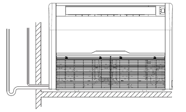
Unità pavimento/soffitto AIR

RICEVIMENTO . . . . . . . . . . . . . . . . . . . . . . . . . . . . . . . . . . . . . . . . . . . . . . . . . . . . . . . . . . . . . . . . . . . . . . . . 3
PREMESSA . . . . . . . . . . . . . . . . . . . . . . . . . . . . . . . . . . . . . . . . . . . . . . . . . . . . . . . . . . . . . . . . . . . . . . . . . . . 3
SCOPO DELL’UNITA’  . . . . . . . . . . . . . . . . . . . . . . . . . . . . . . . . . . . . . . . . . . . . . . . . . . . . . . . . . . . . . . . . . . . 3
DIRETTIVE EUROPEE . . . . . . . . . . . . . . . . . . . . . . . . . . . . . . . . . . . . . . . . . . . . . . . . . . . . . . . . . . . . . . . . . . 3
DATI TECNICI . . . . . . . . . . . . . . . . . . . . . . . . . . . . . . . . . . . . . . . . . . . . . . . . . . . . . . . . . . . . . . . . . . . . . . . . . 4
DIMENSIONI DI INGOMBRO . . . . . . . . . . . . . . . . . . . . . . . . . . . . . . . . . . . . . . . . . . . . . . . . . . . . . . . . . . . . . 5
DESCRIZIONE UNITÀ  . . . . . . . . . . . . . . . . . . . . . . . . . . . . . . . . . . . . . . . . . . . . . . . . . . . . . . . . . . . . . . . . . . 5
NORME DI SICUREZZA . . . . . . . . . . . . . . . . . . . . . . . . . . . . . . . . . . . . . . . . . . . . . . . . . . . . . . . . . . . . . . . . . 6
IMBALLO E IMMAGAZZINAMENTO . . . . . . . . . . . . . . . . . . . . . . . . . . . . . . . . . . . . . . . . . . . . . . . . . . . . . . . . 7
CONTENUTO . . . . . . . . . . . . . . . . . . . . . . . . . . . . . . . . . . . . . . . . . . . . . . . . . . . . . . . . . . . . . . . . . . . . . . . . . 7
REFRIGERANTE R32: NOTE ALL’INSTALLAZIONE . . . . . . . . . . . . . . . . . . . . . . . . . . . . . . . . . . . . . . . . . . . 7
INSTALLAZIONE . . . . . . . . . . . . . . . . . . . . . . . . . . . . . . . . . . . . . . . . . . . . . . . . . . . . . . . . . . . . . . . . . . . . . . . 8
SCELTA DEL LUOGO DI INSTALLAZIONE DELL’UNITA’ INTERNA . . . . . . . . . . . . . . . . . . . . . . . . . . . . . . . 9
SPAZI MINIMI OPERATIVI  . . . . . . . . . . . . . . . . . . . . . . . . . . . . . . . . . . . . . . . . . . . . . . . . . . . . . . . . . . . . . . . 10
INSTALLAZIONE  . . . . . . . . . . . . . . . . . . . . . . . . . . . . . . . . . . . . . . . . . . . . . . . . . . . . . . . . . . . . . . . . . . . . . . 11
CONSIGLI PER UNA CORRETTA INSTALLAZIONE  . . . . . . . . . . . . . . . . . . . . . . . . . . . . . . . . . . . . . . . . . . 12
FILTRO ARIA STANDARD  . . . . . . . . . . . . . . . . . . . . . . . . . . . . . . . . . . . . . . . . . . . . . . . . . . . . . . . . . . . . . . . 13
COLLEGAMENTO ELETTRICO . . . . . . . . . . . . . . . . . . . . . . . . . . . . . . . . . . . . . . . . . . . . . . . . . . . . . . . . . . . 13
COLLEGAMENTO ELETTRICO UNITA’ INTERNA . . . . . . . . . . . . . . . . . . . . . . . . . . . . . . . . . . . . . . . . . . . . . 13
SCHEMI DI COLLEGAMENTO . . . . . . . . . . . . . . . . . . . . . . . . . . . . . . . . . . . . . . . . . . . . . . . . . . . . . . . . . . . . 14
CAVI DI COLLEGAMENTO ELETTRICO . . . . . . . . . . . . . . . . . . . . . . . . . . . . . . . . . . . . . . . . . . . . . . . . . . . . 15
INSTALLAZIONE UNITA’ ESTERNA . . . . . . . . . . . . . . . . . . . . . . . . . . . . . . . . . . . . . . . . . . . . . . . . . . . . . . . . 15
COLLEGAMENTI FRIGORIFERI  . . . . . . . . . . . . . . . . . . . . . . . . . . . . . . . . . . . . . . . . . . . . . . . . . . . . . . . . . . 15

2                                                 Cod. 3QE45970 - Rev. 00 - 05/2019
Unità pavimento/soffitto AIR
RICEVIMENTO
Al momento del ricevimento dell’unità è indispensabile controllare di aver ricevuto tutto il materiale indicato sul documento
d’accompagnamento, ed inoltre che la stessa non abbia subito danni durante il trasporto. In caso affermativo, far costatare
allo spedizioniere l’entità del danno subito, avvertendo nel frattempo il nostro ufficio gestione clienti. Soltanto agendo in questo
modo e tempestivamente sarà possibile avere il materiale mancante o il risarcimento dei danni.

PREMESSA
Il condizionatore è una macchina progettata e costruita esclusivamente per la climatizzazione e deve essere usata solo per
tale scopo. La macchina può funzionare bene e lavorare con profitto soltanto se usata correttamente e mantenuta in piena
efficienza. Preghiamo perciò di leggere attentamente questo libretto d’istruzioni e di rileggerlo ogni qualvolta, nell’usare l’unità,
sorgeranno delle difficoltà o dei dubbi. In caso di necessità ricordiamo comunque che il nostro servizio d’assistenza, organizzato
in collaborazione con i nostri concessionari, è sempre a disposizione per eventuali consigli e interventi diretti.

SCOPO DELL’UNITA’
Il condizionatore descritto in questo manuale è un climatizzatore aria/aria del tipo split, va quindi collegato ad una unità esterna.
L’unità interna diffonde l’aria trattata nell’ambiente da climatizzare mentre l’unità esterna è l’elemento che disperde nell’ambiente
esterno il calore prelevato dall’ambiente interno (modo Raffrescamento) oppure assorbe il calore dall’ambiente esterno per
riscaldare l’ambiente interno (modo Riscaldamento).
NOTA
Una volta collegato all’unità esterna il condizionatore sarà carico di refrigerante R32 parzialmente infiammabile. Il non appro-
priato uso dell’apparecchio comporta il rischio di gravi danni di persone e materiale. Dettagli a questo refrigerante si trovano
nella sezione “Sicurezza e inquinamento”.

DIRETTIVE EUROPEE
L’azienda dichiara che le macchine in oggetto sono conformi a quanto prescritto dalle seguenti direttive, e successive modificazioni:
• Direttiva bassa tensione 2014/35/EU;
• Direttiva compatibilità elettromagnetica 2014/30/EU
• Direttiva 2009/125/EC (EU) sull’Efficienza Energetica;
• Direttiva 2002/96/CE WEE;
• Direttiva 2011/65/EU RoHS.
E risulta conforme a quanto indicato nelle Normativa
• EN 60335-2-40

                                              Cod. 3QE45970 - Rev. 00 - 05/2019                                  IT                3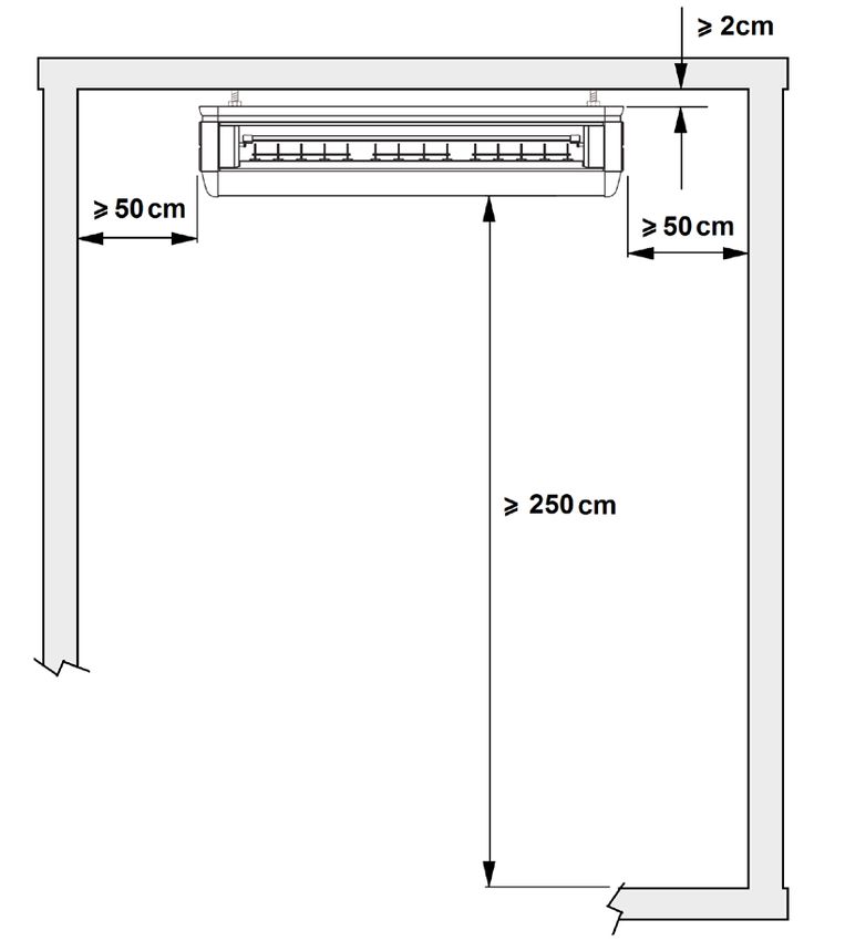
Unità pavimento/soffitto AIR
DATI TECNICI
    Mod.                                          18              24              36         42         48            60       UM
                                   Nom           5000            7000           10550      12100      14000         16000      W
                       Resa                                                    2900 -     2900 -     4760 -        4760 -
                                      Min-Max 1530 - 5600     2160 - 8200                                                       W
    Funzionamento                                                               13000      13500      16500         17500
                                      Nom          1630          2250            3400       4500       5300          6110       W
    a Freddo           Assorbimento
                                      Min-Max 470 - 2300      670 - 3560     710 - 4710 710 - 5100 1710 - 6700   1710 - 6800    W
                                      Nom           7,16          9,88            15        19,5        23           26,5        A
                       Corrente
                                      Min-Max 2,25 - 10,1     3,21 - 15,63    3,2 - 21,5 3,2 - 22,3 7,4 - 28,6    7,4 - 29,1     A
    Deumidificazione                  Nom            2,1           2,5            3,6        4,6        5,6           7,0       l/h
    EER rif. Standard EN14511 Nom                   3,07          3,11           3,10       2,69       2,64          2,62      W|W
    SEER rif. Standard EN14825 Nom                   6,1           6.3            6.1        6,1        6,1           6,1      W|W
    PdesigC                                         5,00          7,00          10,60      11,50      14,00         16,00      kW
                                      Nom          5600          8000           11150      13500      16000         17000       W
                       Resa                                                    2600 -     2600 -     4780 -        4780 -
                                      Min-Max 1400 - 6200     1980 - 9300                                                       W
    Funzionamento                                                               13500      15000      16150         18500
                                      Nom          1730          2100            3450       4600       5500          5900       W
    a Caldo            Assorbimento
                                      Min-Max 460 - 2250      650 - 3620     470 - 4130 470 - 4530 1710 - 6800   1710 - 7100    W
                                      Nom            7,6         9,22            15,5        20        23,9          25,6       A
                       Corrente
                                      Min-Max 2,2 - 9,88      3,11 - 15,9     2,43 - 18 2,43 - 19,7 7,4 - 29,1    7,4 - 29,5    A
    COP rif. Standard EN14511 Nom                   3,24         3,81            3,23       2,93       2,91          2,88      W|W
    SCOP rif. Standard EN14825 Nom                   4,1          4,1             4,0        4,0        4,0           4,0      W|W
    PdesigH                                         5,00         6,80           10,00      10,00      12,50         12,50      kW
    Zona climatica di riferimento rif. Standard
                                                                                 A ( temperata)                                Tipo
    EN14825
    Temp di equilibrio Tbiv                          -7            -7            -7          -7          -7           -7       °C
    Temp limite utilizzo Tol                        -10           -10           -10         -10         -10          -10       °C
    Classe di efficienza sec-
                                      a Freddo      A++          A++           A++            \          \            \         \
    ondo Regolamento attuativo
    626/2011 relativo alla Direttiva a Caldo         A+           A+            A+            \          \            \         \
    2009/125/CE
    Classe di efficienza sec-
                                      a Freddo        \            \             \         249,7       251,1        248,5       %
    ondo Regolamento attuativo
    2016/2281 relativo alla Diret- a Caldo            \            \             \         160,8       163,7        161,9       %
    tiva 2009/125/CE
    Consumo in stand-by                              4,6           4,6          4,6          4,6           8            8        W
                                                 900 - 730    1300 - 1050 1800 - 1550 1800 - 1550 1900 - 1600 1900 - 1600
    Portata aria Max-Med-Min                                                                                                    m3/h
                                                   - 650         - 920        - 1350       - 1350       - 1400       - 1400
    Pressione sonora Max-Med-Min                45 - 40 -34   47 - 43 -3 8 53 - 50 - 47 53 - 50 - 47 54 - 51 - 48 54 - 51 - 48 dB(A)
    Potenza sonora Max                               56            57           63           63           64           64      dB(A)
    Dimensioni imballo                LxDxH 1010×720×290      1360×720×290 1710×720×290 1710×720×290 1710×720×290 1710×720×290 mm
    Peso netto                                       25            32           44           44           44           44        kg
    Peso lordo                                       28            38           50           50           50           50        kg

In raffreddamento Temperatura aria ambiente 27°C B.S 19°C B.U Temperatura esterna 35°C B.S
In riscaldamento Temperatura aria ambiente 20°C B.S Temperatura esterna 7°C B.S 6°C B.U
*: Pressione sonora rilevata ad 1 metro di distanza: in ambiente di 100m3 con tempo di riverbero di 0.5 secondi.

4                 IT                            Cod. 3QE45970 - Rev. 00 - 05/2019
Unità pavimento/soffitto AIR
DIMENSIONI DI INGOMBRO
fig. 1
Mod. 18 24 36 42 48 60 U.M
L 929 1280 1631 mm
H 660 mm
P 205 mm
DESCRIZIONE UNITÀ
1.GRUPPO VENTILANTE
Il gruppo ventilante è composto da un unico motore e più ventole centrifughe, a seconda del modello.
2.BATTERIA DI SCAMBIO TERMICO
La batteria di scambio termico è realizzata in tubo di rame ed alettature a pacco continuo in lamierino
d’alluminio. Le alette sono bloccate in modo diretto, mediante espansione meccanica del tubo di rame, per ottenere un’elevata
trasmissione di calore.
3.SEZIONE FILTRANTE
La sezione filtrante, presente nell’unità interna, è costituita da materiale sintetico ad alto potere filtrante, ed è rigenerabile
tramite soffiatura e lavaggio.
4.COMANDO
L’unità è fornita di serie con un comando a raggi infrarossi. Esso consente di operare con facilità e di avere sotto controllo
tutti i parametri di funzionamento.
fig. 2
Cod. 3QE45970 - Rev. 00 - 05/2019 IT 5Unità pavimento/soffitto AIR NORME DI SICUREZZA Le norme sotto indicate vanno seguite attentamente per evitare danni all’operatore e alla macchina. • L’installazione della macchina deve essere eseguita secondo le norme di impiantistica nazionale • Il presente manuale dell’installatore, il manuale dell’utente e gli schemi elettrici sono parte integrante della macchina. Tutti insieme devono essere custoditi e conservati con cura affinché siano disponibili agli operatori per le consultazioni necessarie. • La mancata osservanza di quanto descritto in questo manuale ed un’inadeguata installazione del condizionatore, possono essere causa d’annullamento del certificato di garanzia. La Ditta Costruttrice inoltre non risponde d’eventuali danni diretti e/o indiretti dovuti ad errate installazioni. • Ogni intervento di manutenzione straordinaria deve essere eseguito da personale specializzato ed abilitato. • Durante l’installazione operare in ambiente pulito e libero da impedimenti. • Evitare assolutamente di toccare le parti in movimento o di interporsi tra le stesse. • Prima di mettere in funzione il condizionatore, controllare la perfetta integrità e sicurezza dei vari componenti e dell’intero impianto. • Eseguire scrupolosamente la manutenzione ordinaria. • In caso si devono sostituire dei pezzi, richiedere sempre ricambi originali. In caso contrario la garanzia decade. • Non rimuovere o manomettere i dispositivi di sicurezza. • Prima di eseguire qualsiasi intervento sulla macchina togliere l’alimentazione elettrica. • Si eviti di appoggiare qualsiasi oggetto sulla parte superiore delle unità. • Non inserire o far cadere oggetti attraverso le griglie di protezione dei ventilatori. • La superficie della batteria è tagliente. Non toccare senza protezioni. • Leggere attentamente le etichette sulla macchina, non coprirle per nessuna ragione e sostituirle in caso fossero danneggiate. • Non usare la macchina in atmosfera esplosiva. • La linea d’alimentazione deve essere provvista di messa a terra regolamentare. • Nel momento in cui si riscontrasse un danneggiamento al cavo d’alimentazione bisogna spegnere la macchina, se si è in fase di lavoro, e farlo sostituire da un tecnico autorizzato. • La temperatura d’immagazzinamento deve essere compresa tra i -25°C e i 55°C. • In caso d’incendio usare un estintore a polvere. Non usare acqua. • Nel momento in cui si dovessero riscontrare anomalie nel funzionamento della macchina accertarsi che non siano dipendenti dalla mancata manutenzione ordinaria. In caso contrario richiedere l’intervento di un tecnico specializzato. • Ogni intervento di manutenzione straordinaria deve essere eseguito da personale specializzato ed abilitato. • La macchina non deve essere abbandonata, in fase di rottamazione, per la presenza di materiali soggetti a norme che ne prevedono il riciclaggio o lo smaltimento presso centri appositi. • Non lavare la macchina con getti d’acqua diretti o in pressione o con sostanze corrosive. La Ditta costruttrice, con la sua rete d’assistenza, è comunque a disposizione per assicurare una pronta ed accurata assistenza tecnica e tutto quanto può essere utile per il miglior funzionamento ed ottenere il massimo della resa. 6 IT Cod. 3QE45970 - Rev. 00 - 05/2019
Unità pavimento/soffitto AIR
IMBALLO E IMMAGAZZINAMENTO
Tutti i modelli sono provvisti d’appositi imballi in cartone specifici
per ogni unità.
Sugli imballi sono riportate tutte le indicazioni necessarie per
una corretta movimentazione durante l’immagazzinamento e
la messa in opera. La temperatura d’immagazzinamento deve
essere compresa tra -25°C e 55°C.
N.B.: Non disperdere gli imballi nell’ambiente.
Una volta deciso il luogo d’installazione (vedi in seguito i
paragrafi relativi), per sballare l’unità procedere come segue:
1.Tagliare le due regge in nylon.
2.Aprire il lato superiore dell’imballo.
3.Afferrare l’unità e sollevarla fino ad ottenerne l’estrazione
completa dall’imballo stesso.
4.Togliere le protezioni e sfilare l’involucro in nylon. fig. 3
CONTENUTO
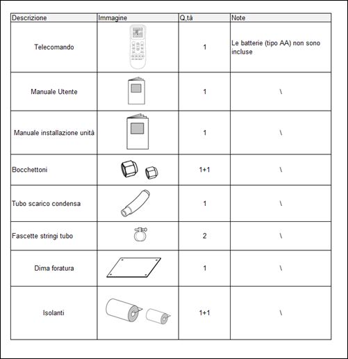
Oltre alle unità all’interno degli imballi sono contenuti accessori e documentazione tecnica per l’uso e l’installazione. Verificare
che siano presenti i seguenti componenti.
Descrizione Immagine Quantità Notes
Le batterie (tipo AAA) non
Telecomando 1
sono incluse
Manuale utente 1 /
Manuale installazione unità 1 /
Bocchettoni 2 /
Dima foratura 1 /
Isolanti 2 /
REFRIGERANTE R32: NOTE ALL’INSTALLAZIONE
1. Si raccomanda l’installazione del condizionatore in ambienti in cui non possono essere presenti fiamme libere.
2.Non è permesso praticare fori sulle linee frigorifere o avvicinarsi alle tubazioni con fiamme libere.
3. Il condizionatore d’aria deve essere installato in un ambiente con superficie in pianta superiore a quanto riportato nella
seguente tabella 1. (la carica da considerarsi è quella relativa alla macchina più eventuali integrazioni di carica legati alla
lunghezza effettiva delle linee) Nota: La superficie minima richiesta dipende fortemente dalla posizione di installazione ( a
soffitto od a pavimento)
4. Il Test di verifica tenuta dell’impianto frigorifero è d’obbligo dopo l’installazione.
Tab.1
Carica di Refrigerante (kg) ≤1,24 1,25 1,3 1,4 1,5 1,6 1,8 2,0 2,2 2,4 2,6 2,8 3,0 3,2 3,4 3,6 3,8 4,0 4,2 4,4
Pavimento Superficie no limite 1,0 1,1 1,3 1,4 1,6 2,1 2,6 3,1 3,7 4,3 5,0 5,7 6,5 7,4 8,2 9,3 10 12 13
Soffitto minima m² no limite 13 15 17 19 22 28 34 42 49 58 67 77 88 99 112 125 139 153 169
Nota: Nel caso in cui la superficie richiesta sia superiore a quella disponibile è necessario predisporre dei sistemi di aereazione
forzata o sistemi di segnalazione in ottemperanza con le norme locali di sicurezza.
Cod. 3QE45970 - Rev. 00 - 05/2019 IT 7Unità pavimento/soffitto AIR
INSTALLAZIONE
L’installazione può essere eseguita o con le unità interne poste sopra l’unità esterna o viceversa od in alcuni casi con unità
sopra o sotto il livello di installazione dell’unità esterna, come indicato nello schema sui limiti di installazione.
Unità esterna posta in basso ed unità interna in alto (Fig.4).
In questo caso è consigliato eseguire un sifone sulla tubazione d’aspirazione allo scopo di bloccare il deflusso di refrigerante
e di evitare, quindi, ritorni di liquido al compressore.
fig. 4
Unità esterna posta in alto e unità interna in basso (Fig.5).
In questo caso, sulla tubazione d’aspirazione devono essere previsti dei sifoni ogni tre metri di dislivello. Questi sifoni avranno
lo scopo di rendere possibile il ritorno dell’olio al compressore.
fig. 5
Dislivelli ammessi
I massimi dislivelli tra unità interna ed unità esterna e tra unità interne non devono superare i valori indicati nel paragrafo “LIMITI
SU LUNGHEZZA E DISLIVELLO DELLE TUBAZIONI REFRIGERANTI” riportato nel manuale di installazione delle unità esterne.
Lunghezza delle linee frigorifere
La lunghezza delle tubazioni del refrigerante tra le unità interna ed esterna deve essere la piu’ breve possibile, ed è comunque
limitata dal rispetto dei massimi valori di dislivello tra le unità.
Nota: Con la diminuzione del dislivello tra le unità e della lunghezza delle tubazioni, si andranno a limitare le perdite di carico,
aumentando di conseguenza il rendimento complessivo della macchina.
La massima lunghezza delle linee frigorifere e le eventuali cariche integrative di refrigerante sono indicate nel paragrafo “LIMITI
SU LUNGHEZZA E DISLIVELLO DELLE TUBAZIONI REFRIGERANTI” riportato nel manuale di installazione delle unità esterne.
Isolamento delle tubazioni
E’ necessario che le tubazioni di collegamento siano solate
8 IT Cod. 3QE45970 - Rev. 00 - 05/2019Unità pavimento/soffitto AIR
SCELTA DEL LUOGO DI INSTALLAZIONE DELL’UNITA’ INTERNA
Da evitare:
• Posizione soggetta a raggi solari diretti.
• Aree in prossimità di fonti di calore.
• Luoghi umidi e posizioni dove l ‘unità potrebbe venire a contatto con acqua (es:locali adibiti ad uso lavanderia).
• Luoghi dove scaffalature o mobili possano ostruire la circolazione dell’aria.
Da fare:
• Considerare un ‘area libera da ostruzioni che potrebbero compromettere la regolare mandata e ripresa dell’aria.
• Considerare un ‘area dove le operazioni di installazione siano facilitate.
• Considerare una posizione che rispetti gli spazi minimi di manutenzione consigliati.
• Considerare una posizione che permetta una buona distribuzione dell’aria nell ‘ambiente.
• Installare l ‘unità in modo che l ‘acqua di condensa possa facilmente essere drenata,ad uno scarico adeguato.
• Scegliere una posizione possibilmente centrale al locale;la regolazione dell’uscita dell’aria permetterà di ottimizzare
la distribuzione dell’aria nel locale.
• Generalmente la posizione ottimale delle alette è quella che consente il lancio dell’aria aderente al soffitto per effetto Coanda.
Luogo:
• Installarla su un muro rigido e privo di vibrazioni e quindi metterla a livello.
• Rimuovere eventuali ostacoli davanti all’ingresso aria e alle griglie di uscita.
• Mantenere lontano da fonti di gas, da liquidi infiammabili oppure da sostanze acide o alcaline.
• Non esporre l’unità interna alla luce solare diretta.
• Installare il un luogo dove sia agevole il collegamento con l’ unità esterna.
• Fare in modo che l’acqua di condensa possa defluire facilmente.
• Avvicinare le tubazioni o il cavo di alimentazione.
• Posizionare l’unità interna lontana da fonti di calore o di vapore.
• Non installare il climatizzatore in ambienti ove sono presenti vapori o gas oleosi pesanti.
• Posizionare l’unità interna in un punto da cui l’aria fredda possa essere diffusa in tutta la stanza.
• Posizionare l’unità interna alla distanza di almeno un metro da televisori, radio, apparecchi con telecomando e lampade
fluorescenti.
• Rispettare gli spazi minimi per una corretta installazione e per eventuali manutenzioni
Cod. 3QE45970 - Rev. 00 - 05/2019 IT 9Unità pavimento/soffitto AIR
SPAZI MINIMI OPERATIVI
• Rispettare lo spazio minimo per l’installazione e la manutenzione indicato in Fig.6-7.
fig. 6
fig. 7
10 IT Cod. 3QE45970 - Rev. 00 - 05/2019Unità pavimento/soffitto AIR
INSTALLAZIONE
L’unità può essere posta a soffitto o a pavimento. Una volta scelto dove fissarla procedere come indicato di seguito:
1.Una volta praticati i fori, inserire gli inserti dei prigionieri e
successivamente, fissare i perni di sostegno. Per le distanze dei
fori consultare lo schema riportato di seguito oppure utilizzare
la dima fornita con l’unità.
Mod. 18 24 36 42 48 60 U.M
L1 841 1192 1543 mm
fig. 8
2.Inserire nel prigioniero i 4 dadi per il sostegno provvisorio
dell’unità. Assicurarsi che i ganci siano adeguatamente dimen-
sionati per il peso dell’Unità.
3. Se l’installazione è a soffitto, inserire nei fori i tappi ad espan-
sione e fissare con le viti, in modo sicuro, le staffe di fissaggio.
Si raccomanda di posizionare le staffe il più possibile a livello
facendo riferimento ad angoli o architravi.
4. Se l’installazione è a pavimento inserire i tappi ad espansione
con ganci di supporto.
5. L’uscita dei tubi di collegamento frigorifero e dei cavi elettrici
può essere selezionata tra quelle indicate in figura.
Per la posizione A e B togliere i pre-tranci a e b sul cabinet
metallico, per la posizione C togliere il pre-trancio c sulla fiancata
in plastica dell’unità. fig. 9
6. Togliere i fianchi c dell’unita e predisporre per il fissaggio
delle staffe a al telaio dell’unità.
7. Avvitare, in modo parziale, sui lati dell’unità le viti (b) neces-
sarie per la sospensione alle staffe
8. Agganciare l’unità e fissare le viti.
9. Controllare la stabilità muovendo l’unità verso destra e
verso sinistra.
10. Eseguire l’allacciamento dei tubi di collegamento con quelli
dell’unità interna, lubrificando con olio frigorifero le cartelle e
coprendo accuratamente il punto d’unione con del materiale
termoisolante.
11. Collegare il tubo scarico condensa nel raccordo della
bacinella di raccolta e farlo uscire passandolo attraverso il foro
praticato nel muro. A seconda delle esigenze personali tale tubo
può essere convogliato anche in altre direzioni, a condizione
che sia sempre rispettata una minima pendenza per consentire fig. 10
il regolare deflusso della condensa.
Cod. 3QE45970 - Rev. 00 - 05/2019 IT 11Unità pavimento/soffitto AIR
CONSIGLI PER UNA CORRETTA INSTALLAZIONE
Dopo l’installazione dell’unità interna, è necessario verificarne l’orizzontalità.
- Garantire una minima inclinazione, verso il lato di deflusso
per evitare ristagni di acqua nella bacinella (fig.11).
fig. 11
-Evitare formazioni di dossi o rialzamenti sul tubo di scarico
(fig.12).
fig. 12
- E’ consigliabile eseguire un sifone sulla tubazione di scarico
condensa, in modo da evitare risalite di odori (fig.13).
fig. 13
Assicurarsi di isolare il punto in cui sono collegati l’attacco con il tubo di scarico (fig.14).
Anche la porta di scarico inutilizzata deve essere isolata correttamente (fig.15)
Utilizzare i quadrotti d’isolante adesivo in modo che si possa applicarlo direttamente al tubo di scarico.
fig. 15
fig. 14
Dopo aver terminato il collegamento delle tubazioni di scarico, controllare se il drenaggio funziona correttamente e senza intoppi.
12 IT Cod. 3QE45970 - Rev. 00 - 05/2019Unità pavimento/soffitto AIR
FILTRO ARIA STANDARD
Le unità sono dotate di filtri standard di serie. Per l’estrazione
dei filtri e la loro pulizia operare secondo figura 16.
fig. 16
COLLEGAMENTO ELETTRICO
Caratteristiche elettriche generali
• Derivare una linea di alimentazione per il solo condizionatore, provvista di un dispositivo di protezione automatico (interruttore
magnetotermico per carichi industriali), a carico dell’utente, posizionato a monte della linea stessa.
• Accertarsi che il voltaggio della linea di alimentazione corrisponda alle esigenze riportate nei dati di targa.
• La linea di alimentazione di tutti i modelli deve essere provvista di un conduttore di protezione (messa a terra) opportuna-
mente dimensionato.
• Le linee che alimentano i carichi fissi della macchina (compressore, ventilatori, ecc.) sono state dimensionate secondo le
normative vigenti per quanto riguarda la protezione contro i sovraccarichi e i cortocircuiti.
• Si raccomanda di collegare i conduttori provenienti dalla sorgente di alimentazione direttamente ai morsetti di ingresso del
dispositivo di sezionamento dell’alimentazione (fare riferimento agli schemi elettrici a corredo macchina)
• I quadri elettrici sono dotati di un morsetto per il collegamento del conduttore di protezione, identificato dalla marcatura.
Collegamenti elettrici
Per permettere l’avviamento del condizionatore è necessario effettuare i collegamenti elettrici come da schemi elettrici a
corredo macchina. E’ indispensabile che le due unità siano collegate ad un’efficiente presa di terra. Il costruttore declina ogni
responsabilità per la non osservanza di questa precauzione.
N.B.: Per qualsiasi intervento sull’impianto elettrico riferirsi agli schemi elettrici a corredo macchina. Per i collegamenti
elettrici e il collegamento al comando attenersi alle specifiche riportate nelle tabelle sottostanti.
COLLEGAMENTO ELETTRICO UNITA’ INTERNA
1. Aprire la griglia frontale.
2. Rimuovere il copri scheda.
3. Inserire il cavi dal lato posteriore o inferiore a seconda
dell’installazione.
4. Effettuare i collegamenti facendo riferimento agli schemi
elettrici relativi all’unità.
5. Riposizionare le viti, e richiudere il tutto. Per l’inserimento dei
cavi nella morsettiera è necessario premere con un cacciavite
nell’apposita sede, inserire il tratto sguainato e rilasciare il
cacciavite. Verificare il fissaggio.
N.B.:Il filo giallo/verde di terra deve essere almeno 20 mm più fig. 17
lungo degli altri fili.
Cod. 3QE45970 - Rev. 00 - 05/2019 IT 13Unità pavimento/soffitto AIR
SCHEMI DI COLLEGAMENTO
Negli schemi sotto, indicazione dei collegamenti da eseguire in fase di installazione
Mod. 18-24-36-42 monofase
fig. 18
Mod. 48-60 trifase
fig. 19
14 IT Cod. 3QE45970 - Rev. 00 - 05/2019Unità pavimento/soffitto AIR
CAVI DI COLLEGAMENTO ELETTRICO
Tipo di cavo consigliato H05RN-F o secondo installazione vedere normative specifiche.
Interruttore automatico a cura dell’installatore, con potere d’interruzione come da tabella
Mod. 18 24 36 42 48 60 U.M
Tipo di alimentazione 230/1/50 400/3/50 V-ph-Hz
IG1 10 A
Interruttore automatico
IG2 25 40 20 A
A 3 x 2,5 5 x 2,5 mm2
Sezione cavo B 3 x 1,5 mm2
C 2 x 0,5 mm2
INSTALLAZIONE UNITA’ ESTERNA
Per i dettagli sulla installazione dell’unità esterna si veda il manuale di installazione della madesima
COLLEGAMENTI FRIGORIFERI
Per i dettagli sui collegamenti frigoriferi si veda il manuale di installazione dell’unità esterna
Cod. 3QE45970 - Rev. 00 - 05/2019 IT 15AIR floor/ceiling unit DELIVERY OF THE MACHINE . . . . . . . . . . . . . . . . . . . . . . . . . . . . . . . . . . . . . . . . . . . . . . . . . . . . . . . . . . . . 17 FOREWORD . . . . . . . . . . . . . . . . . . . . . . . . . . . . . . . . . . . . . . . . . . . . . . . . . . . . . . . . . . . . . . . . . . . . . . . . . . 17 PRESENTATION OF THE UNIT . . . . . . . . . . . . . . . . . . . . . . . . . . . . . . . . . . . . . . . . . . . . . . . . . . . . . . . . . . . 17 DECLARATION OF CONFORMITY . . . . . . . . . . . . . . . . . . . . . . . . . . . . . . . . . . . . . . . . . . . . . . . . . . . . . . . . 17 TECHNICAL DATA . . . . . . . . . . . . . . . . . . . . . . . . . . . . . . . . . . . . . . . . . . . . . . . . . . . . . . . . . . . . . . . . . . . . . 18 DIMENSIONAL DATA . . . . . . . . . . . . . . . . . . . . . . . . . . . . . . . . . . . . . . . . . . . . . . . . . . . . . . . . . . . . . . . . . . . 19 DESCRIZIONE UNITÀ . . . . . . . . . . . . . . . . . . . . . . . . . . . . . . . . . . . . . . . . . . . . . . . . . . . . . . . . . . . . . . . . . . 19 SAFETY REGULATIONS . . . . . . . . . . . . . . . . . . . . . . . . . . . . . . . . . . . . . . . . . . . . . . . . . . . . . . . . . . . . . . . . 20 PACKING AND STORING . . . . . . . . . . . . . . . . . . . . . . . . . . . . . . . . . . . . . . . . . . . . . . . . . . . . . . . . . . . . . . . . 21 CONTENT . . . . . . . . . . . . . . . . . . . . . . . . . . . . . . . . . . . . . . . . . . . . . . . . . . . . . . . . . . . . . . . . . . . . . . . . . . . . 21 REFRIGERANT R32: INSTALLATION NOTES . . . . . . . . . . . . . . . . . . . . . . . . . . . . . . . . . . . . . . . . . . . . . . . . 21 INSTALLATION . . . . . . . . . . . . . . . . . . . . . . . . . . . . . . . . . . . . . . . . . . . . . . . . . . . . . . . . . . . . . . . . . . . . . . . . 22 CHOICE OF THE INSTALLATION SITE FOR THE INDOOR UNIT . . . . . . . . . . . . . . . . . . . . . . . . . . . . . . . . 23 MINIMUM OPERATING UNIT SPACES . . . . . . . . . . . . . . . . . . . . . . . . . . . . . . . . . . . . . . . . . . . . . . . . . . . . . 24 INSTALLATION SITE OF THE INDOOR UNIT . . . . . . . . . . . . . . . . . . . . . . . . . . . . . . . . . . . . . . . . . . . . . . . . 25 TIPS FOR A PROPER INSTALLATION . . . . . . . . . . . . . . . . . . . . . . . . . . . . . . . . . . . . . . . . . . . . . . . . . . . . . 26 STANDARD AIR FILTER . . . . . . . . . . . . . . . . . . . . . . . . . . . . . . . . . . . . . . . . . . . . . . . . . . . . . . . . . . . . . . . . . 27 ELECTRIC CONNECTIONS . . . . . . . . . . . . . . . . . . . . . . . . . . . . . . . . . . . . . . . . . . . . . . . . . . . . . . . . . . . . . . 27 CONNECTION WITH INDOOR UNIT . . . . . . . . . . . . . . . . . . . . . . . . . . . . . . . . . . . . . . . . . . . . . . . . . . . . . . . 27 CONNECTION SCHEME . . . . . . . . . . . . . . . . . . . . . . . . . . . . . . . . . . . . . . . . . . . . . . . . . . . . . . . . . . . . . . . . 28 CONNECTION CABLE . . . . . . . . . . . . . . . . . . . . . . . . . . . . . . . . . . . . . . . . . . . . . . . . . . . . . . . . . . . . . . . . . . 29 INSTALLATION OF OUTDOOR UNIT . . . . . . . . . . . . . . . . . . . . . . . . . . . . . . . . . . . . . . . . . . . . . . . . . . . . . . . 29 REFRIGERANT CONNECTION . . . . . . . . . . . . . . . . . . . . . . . . . . . . . . . . . . . . . . . . . . . . . . . . . . . . . . . . . . . 29 16 Cod. 3QE45970 - Rev. 00 - 05/2019
AIR floor/ceiling unit
DELIVERY OF THE MACHINE
As soon as the machine is delivered, it is essential for the user to make sure that he has received all the items indi¬cated on
the delivery note and that the machine has not been damaged during transport. If damage is discovered, allow the forwarding
agent to ascertain its entity and also inform our seller. Only in this way will you be able to receive the missing items or reim-
bursement of damages within the shortest possible time.

FOREWORD
This air conditioner has been designed and manufactured for air conditioning requirements only and must therefore be used
for this purpose alone. Even the best of machines are capable of operating efficiently and correctly only if they are used in
the correct manner and kept fully efficient. You are therefore kindly requested to carefully read this instruction manual and
to consult it each time difficulties should arise when using the machine or when in doubt. In any event, we remind you that
if necessary, our assistance service, organized in collaboration with our dealer, is always at your disposal for any advice or
direct intervention required.

PRESENTATION OF THE UNIT
The air conditioner described in this manual is a split-type air / air conditioner and must therefore be connected to an indoor unit.
The indoor unit diffuses the treated air into the room to be air-conditioned while the outdoor unit is the element that disperses
the heat taken from the indoor environment (cooling mode) into the external environment or absorbs the heat from the external
environment to heat up the internal environment (Heating mode)
NOTA
Appliance filled with flammable gas R32.
Please notice that the unit is filled with flammable gas R32. Inappropriate treatment of the unit involves the risk of severe
damages of people and material. Details to this refrigerant are found in section “SAFETY AND POLLUTION”

DECLARATION OF CONFORMITY
The manufacturer declares that the machines described in this instruction manual meet the requirements of the
following directives and subsequent modifications.
• Low voltage directive 2014/35/EU;
• Electromagnetic compatibility directive 2014/30/EU;
• Energy Efficiency Directive 2009/125/EC (EU);
• Directive 2002/96/EC WEE;
• Directive 2011/65/EU RoHS.
It conforms to what is stated in the legislation
• EN 60335-2-40

                                              Cod. 3QE45970 - Rev. 00 - 05/2019                                EN                 17
AIR floor/ceiling unit
TECHNICAL DATA
Mod. 18 24 36 42 48 60 UM
Nom 5000 7000 10550 12100 14000 16000 W
Capacity 2900 - 2900 - 4760 - 4760 -
Min-Max 1530 - 5600 2160 - 8200 W
13000 13500 16500 17500
Cooling mode Nom 1630 2250 3400 4500 5300 6110 W
Input
Min-Max 470 - 2300 670 - 3560 710 - 4710 710 - 5100 1710 - 6700 1710 - 6800 W
Nom 7,16 9,88 15 19,5 23 26,5 A
Current
Min-Max 2,25 - 10,1 3,21 - 15,63 3,2 - 21,5 3,2 - 22,3 7,4 - 28,6 7,4 - 29,1 A
Moisture remval Nom 2,1 2,5 3,6 4,6 5,6 7,0 l/h
EER ref. Standard EN14511 Nom 3,07 3,11 3,10 2,69 2,64 2,62 W|W
SEER ref. Standard EN14825 Nom 6,1 6.3 6.1 6,1 6,1 6,1 W|W
PdesigC 5,00 7,00 10,60 11,50 14,00 16,00 kW
Nom 5600 8000 11150 13500 16000 17000 W
Capacity 2600 - 2600 - 4780 - 4780 -
Min-Max 1400 - 6200 1980 - 9300 W
13500 15000 16150 18500
Heating mode Nom 1730 2100 3450 4600 5500 5900 W
Input
Min-Max 460 - 2250 650 - 3620 470 - 4130 470 - 4530 1710 - 6800 1710 - 7100 W
Nom 7,6 9,22 15,5 20 23,9 25,6 A
Current
Min-Max 2,2 - 9,88 3,11 - 15,9 2,43 - 18 2,43 - 19,7 7,4 - 29,1 7,4 - 29,5 A
COP rif. Standard EN14511 Nom 3,24 3,81 3,23 2,93 2,91 2,88 W|W
SCOP rif. Standard EN14825 Nom 4,1 4,1 4,0 4,0 4,0 4,0 W|W
PdesigH 5,00 6,80 10,00 10,00 12,50 12,50 kW
Climate zone ref. Standard EN14825 A ( temperata) Tipo
Tbiv -7 -7 -7 -7 -7 -7 °C
Tol -10 -10 -10 -10 -10 -10 °C
Efficiency class Cooling A++ A++ A++ \ \ \ \
Standard 626/2011
Directive 2009/125/CE Heating A+ A+ A+ \ \ \ \
Efficiency class Cooling \ \ \ 249,7 251,1 248,5 %
Standard 2016/2281
Directive 2009/125/CE Heating \ \ \ 160,8 163,7 161,9 %
Stand-by 4,6 4,6 4,6 4,6 8 8 W
900 - 730 1300 - 1050 1800 - 1550 1800 - 1550 1900 - 1600 1900 - 1600
Air flow Max-Med-Min m3/h
- 650 - 920 - 1350 - 1350 - 1400 - 1400
Sound pressure level (max-med-min) 45 - 40 -34 47 - 43 -3 8 53 - 50 - 47 53 - 50 - 47 54 - 51 - 48 54 - 51 - 48 dB(A)
Sound power level 56 57 63 63 64 64 dB(A)
Packing dimension LxDxH 1010×720×290 1360×720×290 1710×720×290 1710×720×290 1710×720×290 1710×720×290 mm
Net weight 25 32 44 44 44 44 kg
Gross weight 28 38 50 50 50 50 kg
In cooling mode Outdoor air temp = 35 °C B.S.- Room temp.= 27 °C B.S./ 19 °C D.B.
In heating mode Outdoor air temp.= 7 °C B.S./ 6°C D.B - Room air temp.= 20 °C B.S.
*: Acoustic pressure measured in a reverberant room with internal volume 100m3 and reverberation time 0.5 second
18 EN Cod. 3QE45970 - Rev. 00 - 05/2019AIR floor/ceiling unit
DIMENSIONAL DATA
fig. 1
Mod. 18 24 36 42 48 60 U.M
L 929 1280 1631 mm
H 660 mm
P 205 mm
DESCRIZIONE UNITÀ
1. FAN SYSTEM
The unit is provided with one DC brushless motor and two or more centrifugal fans in accordance with different model.
2.HEAT EXCHANGE
In both units the heat exchange bank is made of copper tubing with aluminum sheet fins in a continuous
pack. The fins are directly blocked by the mechanical expansion of the copper tube in order to obtain a high performance in
heat transmission.
3.FILTER
The filters are made up of synthetic material with high filtering power that can be regenerated through blowing and washing.
4.CONTROL
This series of air conditioners is provided with a infra-red remote control. It allows to easily control the unit and monitor all
operating parameters.
fig. 2
Cod. 3QE45970 - Rev. 00 - 05/2019 EN 19AIR floor/ceiling unit SAFETY REGULATIONS Strictly comply with the following regulations to prevent injury to the operator or damage to the machine. • The unit installation must be done according to the installation rules valid in your country. • This installer’s handbook, the user manual and the wiring diagrams are integral part of the machine. They must be kept with care and be ready to hand should the operators require them for consultation. • Failure to comply with the instructions in this manual and inadequate installation of the conditioner may void the certificate of guarantee. Moreover, the Manufacturer shall not be liable for direct and/or indirect damages due to incorrect installation or for damages caused by conditioners installed by inexpert or unauthorized personnel. • If the outdoor unit must be dismantled, it is advisable to have the job done by an authorized technical service center. • Work in a clean, uncluttered place when installing the equipment. • It is absolutely forbidden to touch moving parts or to move between the same. • Before starting the conditioner, make sure that the various components and the entire system are in perfect and safe conditions. • Strictly comply with the routine maintenance operations. • Insist on genuine spare parts. Failure to do so will void the guarantee. • Do not remove or tamper with the safety devices. • Disconnect the electric power source before proceeding with any work on the machine. • Do not place anything on the top part of the units. • Do not push items through the protective fan grilles or allow objects to drop through. • The bank surface is sharp. Do not touch it without protective gloves. • Carefully read the stickers on the machine, never cover them and replace them immediately should they be damaged. • Do not use the machine in an explosive atmosphere. • The power line must be regularly grounded. • If the power cable has been damaged, stop the machine if it is operating, and have the cable immediately replaced by an authorized technician. • The machine must be stored at a temperature between -25°C and 55°C. • Use a powder extinguisher in the event of a fire outbreak. Do not use water. • If the machine operates in an abnormal way, make sure that this does not depend on failure to carry out routine maintenance. Failing this, ask to have the machine checked by a specialized technician. • If the outdoor unit must be dismantled, it is advisable to have the job done by an authorized technical service center. • The machine must not be dumped if it is to be scrapped since it contains materials that must be recycled or disposed of by authorized centers. • Do not wash the machine with direct or pressurized jets of water or with corrosive substances. The Manufacturer and after-sales service network are at your disposal for prompt and accurate technical assistance and for anything else able to ensure the best operation and achieve the utmost efficiency from your machine. 20 EN Cod. 3QE45970 - Rev. 00 - 05/2019
AIR floor/ceiling unit
PACKING AND STORING
All machines are packed in cardboard boxes specific for each unit.
The indications required to correctly handle the appliance while storing and installing
it are written on the packing.
The storage temperature must be between -25°C and 55°C.
Note: Do not throw the packing away exteriors to avoid environmental pollution.
Once the place in which the unit is to be installed has been chosen (see the relative
sections) proceed as follows to unpack the two units:
1.Cut the two nylon straps.
2.Open the upper side of the packing.
3.Take the unit and lift it up until completely out of the packing.

4.Remove the protections and the nylon wrapping.                                                     fig. 3

CONTENT
Packaging contain the units as well as accessories and technical documentation for the use and installation. Check that the
following components are present.
             Description                                    Image                         Quantity              Notes

                                                                                                     Batteries (AAA type) are not
            Wire Control                                                                     1
                                                                                                               included

     Wire control Operation
                                                                                             1                    /
            manual

    Unit installation manual                                                                 1                    /

 Refrigerant connection nuts                                                                 2                    /

 Carton frame for fixing holes                                                               1                    /

               Insulator                                                                     2                    /

REFRIGERANT R32: INSTALLATION NOTES
1.The air conditioner is not allowed to use in a room that has running fire (such as fire source, working coal gas ware, ope-
rating heater).
2.It is not allowed to drill hole or burn the connection pipe.
3.The air conditioner must be installed in a room that is larger than the minimum room area. The minimum room area is
shown on the nameplate or following table 1. (The charge value to be considered is that relating to the units plus any charge
additions linked to the actual length of the lines) Note: The minimum required surface depends strongly on the installation
position (ceiling or floor).
4.Leak test is a must after installation.
Tab.1
Refrigerant Charge (kg)             ≤1,24 1,25 1,3 1,4 1,5 1,6 1,8 2,0 2,2 2,4 2,6 2,8 3,0 3,2 3,4 3,6 3,8 4,0 4,2 4,4
Floor        Minimum               no limite 1,0 1,1 1,3 1,4 1,6 2,1 2,6 3,1 3,7 4,3 5,0 5,7 6,5 7,4 8,2 9,3 10 12 13
Air          area m²               no limite 13 15 17 19 22 28 34 42 49 58 67 77 88 99 112 125 139 153 169
Note: If the required area is greater than the available one, it is necessary to provide for forced ventilation systems or signaling
systems in compliance with local safety regulations.

                                                              Cod. 3QE45970 - Rev. 00 - 05/2019                   EN                21
AIR floor/ceiling unit
INSTALLATION
The indoor unit may be installed on top of the outdoor one and vice versa.
Outdoor unit positioned at the bottom and indoor unit on the top (Fig.4).
In this case a trap must be made on the intake piping to halt the downflow of refrigerant and to avoid liquid returning to the
compressor.
fig. 4
Outdoor unit positioned on top and indoor unit on the bottom (Fig.5)
In this case, traps must be installed on the suction piping, every three meters of difference in level. These traps will allow the
oil to return to the compressor. The connection piping must be insulated.
fig. 5
Difference in levels
The maximum difference in level between the indoor unit and outdoor unit must not exceed the values given in the “LIMITS TO
THE LENGTH AND HEIGHT DIFFERENCE OF REFRIGERANT PIPES” section included on the outdoor units’ installation manual.
Limits to the length and height difference
The length of the refrigerant pipes between the indoor and outdoor units must be as short as possible and is in any case limited
by compliance with the maximum height difference values between the units.
Diminution of the difference in height between the units and the pipe lengths will limit the load losses, consequently increasing
the overall efficiency of the machine.
The maximum length of the refrigerant pipes and additional refrigerant charges are indicated in the paragraph “LIMITS ON
LENGTH AND LEVEL OF REFRIGERATING PIPES” reported in the installation manual of the outdoor unit.
Pipes isolation
The relative connection pipes must be insulated.
22 EN Cod. 3QE45970 - Rev. 00 - 05/2019AIR floor/ceiling unit
CHOICE OF THE INSTALLATION SITE FOR THE INDOOR UNIT
Positions to avoid:
• Places in direct sunlight.
• Positions near heat sources.
• Damp places and positions where the unit could come into contact with water (e.g.: washrooms).
• Places where shelves or furniture could prevent the air from circulating correctly.
What to do:
• Choose a position without obstructions that could hamper the air inlets and outlets.
• Choose a position where the appliance is easy to install.
• Choose a position that complies with the recommended minimum space for maintenance work.
• Choose a position that allows air to freely circulate around the room.
• Install the appliance so that the condensation can be easily drained off.
• Choose a position possibly in the middle of the room. Adjustment of the outlet air can then be optimized to reach all parts
of the room.
• The best position for the fins is usually the one that allows the air to blow on to the ceiling through the Coanda effect.
Place
• Install it on a rigid, vibration-free wall and then level it.
• Remove any obstructions from in front of the air inlet and outlet grilles.
• Keep well away from gas sources, inflammable liquids and from acid or alkaline substances.
• Do not expose the internal unit to direct sunlight.
• Install in a place where it is easy to connect to the exterior unit.
• Make sure that the condensation can flow away easily.
• Move the pipes or power cable near.
• Install the interior unit well away from heat or steam sources.
• Do not install the air conditioner in places where there are vapours or heavy oily gases.
• Install the interior unit in a place where the cold air can be distributed to all parts of the room.
• Set the interior unit at least one meter away from televisions, radios, appliances operated with remote controls and fluore-
scent lamps.
• Respect the minimum distances to ensure proper installation and sufficient access for maintenance.
Cod. 3QE45970 - Rev. 00 - 05/2019 EN 23AIR floor/ceiling unit
MINIMUM OPERATING UNIT SPACES
• Comply with the minimum space for installation and maintenance indicated in Fig.6-7.
fig. 6
fig. 7
24 EN Cod. 3QE45970 - Rev. 00 - 05/2019AIR floor/ceiling unit
INSTALLATION SITE OF THE INDOOR UNIT
The interior unit floor/ceiling may be installed on the ceiling or on the ground. Decide where it is to be installed, then
proceed as follows:
1.Once the holes have been drilled, insert the studs of the studs
and then fix the support pins. See the diagram below for the
distance between the holes or use the installation template.
Mod. 18 24 36 42 48 60 U.M
L1 841 1192 1543 mm
fig. 8
2.Insert the 4 nuts for temporary support of the unit into the
stud. (Fig.9). Ensure the hanger is strong enough to withstand
the weight of the unit.
3. If it is to be installed on the ceiling, insert the pressure
plugs in the holes and fix the securing brackets firmly using
the screws. It is advisable to position the brackets as level as
possible referring to corners or beams.
4. If it is to be installed on the ground, insert the pressure plugs
with supporting hooks.
5.The exit point for the refrigerant pipes and electrical cables
can be selected from those shown in the figure. For positions
A and B, remove the pre-trims a and b on the metal cabinet, for
position C remove the pre-cut c on the plastic side of the unit fig. 9
6. Remove the sides c of the unit and prepare for fixing the
brackets a to the unit frame.
7. Screw, the screws (b) to the sides of the unit required to
hang it on the brackets.
8. Hang the unit and tighten the screws.
9. Make sure that it is firm by moving it towards the left and right.
10. Hook up the connection pipes with those of the interior unit,
lubricating the flares with coolant oil and carefully covering the
joint with thermal insulating material.
11. Connect the condensation drain pipe to the fitting of the
collecting tray (1) pulling it out of the hole drilled in the wall.
Depending on individual requirements, this pipe may also be
routed in other directions, provided that it slopes
sufficiently to allow the condensation to flow down.
fig. 10
Cod. 3QE45970 - Rev. 00 - 05/2019 EN 25AIR floor/ceiling unit
TIPS FOR A PROPER INSTALLATION
After installing the indoor unit, it is necessary to check the horizontal position.
-Ensure a minimum inclination towards the outflow side to avoid
water stagnation in the basin (fig.11).
fig. 11
-Ensure a minimum slope towards the downflow side to prevent
water stagnating in the tray (fig.12).
fig. 12
- Avoid rises or ridges in the drain pipe (fig.13).
fig. 13
It is advisable to have a trap on the condensate drain pipe, to prevent odours (fig.14).
The unused drain port also should be insulated properly (Fig.15) There is adhesive on one side of the insulation so that after
removing the protective paper over it the insulation can be directly attached to the drain hose.
fig. 15
fig. 14
After piping work is finished, check if drainage flows smoothly.
26 EN Cod. 3QE45970 - Rev. 00 - 05/2019AIR floor/ceiling unit
STANDARD AIR FILTER
The units are equipped with standard standard filters. To extract
the filters and clean them, proceed according to figure 16.
fig. 16
ELECTRIC CONNECTIONS
General information
• The customer must provide a separate power line for the conditioner fitted with an automatic safety device (heavy-duty circuit
breaker) upstream the line.
• Make sure that the power line voltage matches that indicated on the rating plate.
• The power line of all the models must be fitted with a suitably sized earth connector.
• The lines powering the fixed loads of the unit (compressor, fans, etc.) have been sized according to current legislation gover-
ning overload and short circuit protection.
• The conductors from the power supply running directly to the input terminals of the general switch must be connected (consult
the wiring diagrams supplied with the unit).
• The electrical panels are fitted with a terminal for connecting the earth wire, identified by the marking .
Connection
To allow the conditioner to start, make the electrical connections as shown in the wiring diagrams supplied with the unit.The
two units must be connected to an efficient earth circuit.The maker declines all liability if this precaution is ignored.
Note: When working on the electrical system, refer to the wiring diagrams supplied with the unit
For connections to the power and control circuits, comply with the specifications shown in the following tables.
CONNECTION WITH INDOOR UNIT
1. Open the front grille.
2. Remove the board cover.
3. Insert the wires through from the rear side or bottom, depen-
ding on the installation.
4. Make the connections with reference to the relative wiring
diagrams.
5. Fit the screws back in position and then fit all the parts back
in place. To insert the wires into the terminal board, press on
the relative cavity with a screwdriver, fit in the stripped wire end
and then release the screwdriver. Make sure that everything
is firmly fixed.
fig. 17
NOTE: The yellow/green ground wire must be at least 20 mm
longer than the other wires.
Cod. 3QE45970 - Rev. 00 - 05/2019 EN 27AIR floor/ceiling unit
CONNECTION SCHEME
In the diagrams below, indication of the connections to be performed during installation
Mod. 18-24-36-42 monophase
Outdoor unit
Indoor unit
fig. 18
Mod. 48-60 threephase
Outdoor unit
Indoor unit
fig. 19
28 EN Cod. 3QE45970 - Rev. 00 - 05/2019AIR floor/ceiling unit
CONNECTION CABLE
Recommended type of cable H05RN-F or depending on the installation. See specific standards.
Automatic circuit-breaker at installer’s charge.
Mod. 18 24 36 42 48 60 U.M
Type of power supply 230/1/50 400/3/50 V-ph-Hz
IG1 10 A
Automatic switch
IG2 25 40 20 A
A 3 x 2,5 5 x 2,5 mm2
Cable section B 3 x 1,5 mm2
C 2 x 0,5
INSTALLATION OF OUTDOOR UNIT
For details on installing the outdoor, see the installation manual of the outdoor unit
REFRIGERANT CONNECTION
For details on refrigerant connection, see the installation manual of the outdoor unit
Cod. 3QE45970 - Rev. 00 - 05/2019 EN 29Certificato di Garanzia
La presente garanzia convenzionale è valida per gli apparecchi destinati alla
commercializzazione, venduti ed installati sul solo territorio italiano
La Direttiva Europea 99/44/CE ha per oggetto taluni aspetti della vendita e delle garanzie dei beni di consumo e regolamenta il rapporto tra venditore finale e consumatore. La
direttiva in oggetto prevede che in caso di difetto di conformità del prodotto, il consumatore ha diritto a rivalersi nei confronti del venditore finale per ottenerne il ripristino senza
spese, per un periodo di 24 mesi dalla data di acquisto.
Ferroli S.p.A., pur non essendo venditore finale nei confronti del consumatore, intende comunque supportare le responsabilità del venditore finale con una propria Garanzia
Convenzionale, fornita tramite la propria Rete di Assistenza Tecnica Autorizzata alle condizioni riportate di seguito.
Oggetto della Garanzia e Durata
L’oggetto della presente garanzia convenzionale consiste nel ripristino della conformità del bene senza spese per il consumatore, alle condizioni qui di seguito specificate.
L’Azienda produttrice garantisce dai difetti di fabbricazione e di funzionamento gli apparecchi venduti ai consumatori per un periodo di 24 mesi dalla data di consegna, purché
avvenuta entro 3 anni dalla data di fabbricazione del prodotto e documentata attraverso regolare documento di acquisto.
Modalità per far valere la presente Garanzia
In caso di guasto, il cliente deve richiedere entro il termine di decadenza di 30 giorni l'intervento del Centro Assistenza di zona, autorizzato Ferroli S.p.A.
I nominativi dei Centri Assistenza autorizzati sono reperibili:
• attraverso il sito internet dell'azienda costruttrice;
• attraverso il numero verde 800-59-60-40.
I Centri Assistenza e/o l’Azienda produttrice potranno richiedere di visionare il documento fiscale di acquisto: conservare pertanto con cura tali documenti per tutta la durata della
garanzia. I costi di intervento sono a carico dell'azienda produttrice, fatte salve le esclusioni previste e riportate nel presente Certificato, Gli interventi in garanzia non modificano la
data di decorrenza della Garanzia e non prolungano la durata della stessa.
Esclusioni
Sono esclusi dalla presente garanzia i difetti di conformità causati da:
trasporto non effettuato a cura dell'azienda produttrice;
anormalità o anomalie di qualsiasi genere nell’alimentazione degli impianti idraulici, elettrici e scarichi;
calcare, inadeguati trattamenti dell’acqua e/o trattamenti disincrostanti erroneamente effettuati;
corrosioni causate da condensa o aggressività dell’acqua;
gelo, correnti vaganti e/o effetti dannosi di scariche atmosferiche;
mancanza di dispositivi di protezione contro le scariche atmosferiche;
trascuratezza, incapacità d’uso o manomissioni/modifiche effettuate da personale non autorizzato;
cause di forza maggiore indipendenti dalla volontà e dal controllo dell'azienda produttrice
E’ esclusa qualsiasi responsabilità dell’Azienda produttrice per danni diretti e/o indiretti, a qualsiasi titolo dovuti.
La presente Garanzia Convenzionale decade nel caso di :
assenza del documento fiscale d’acquisto
inosservanza delle istruzioni e delle avvertenze previste dall'azienda produttrice e riportate sui manuali di utilizzo a corredo del prodotto;
errata installazione o inosservanza delle prescrizioni di installazione, previste dall’Azienda produttrice e riportate sui manuali di installazione a corredo del prodotto;
inosservanza di norme e/o disposizioni previste da leggi e/o regolamenti vigenti, in particolare per assenza o difetto di manutenzione periodica;
interventi tecnici effettuati sul prodotto da soggetti estranei alla Rete di Assistenza Autorizzata dall’Azienda produttrice;
impiego di parti di ricambio non originali Ferroli S.p.A.;
Non rientrano nella presente Garanzia Convenzionale la sostituzione delle parti soggette a normale usura di impiego (anodi, guarnizioni, manopole, lampade spia, resistenze
elettriche, ecc …), le operazioni di pulizia e manutenzione ordinaria e le eventuali attività o operazioni per accedere al prodotto (smontaggio mobili o coperture, allestimento ponteggi,
noleggio gru/cestelli, ecc.).
Responsabilità
Il personale autorizzato dalla azienda produttrice interviene a titolo di assistenza tecnica nei confronti del Cliente; l'installatore resta comunque l'unico responsabile dell'installazione
che deve rispettare le prescrizioni di legge e le prescrizioni tecniche riportate sui manuali di installazione a corredo del prodotto.
Le condizioni di garanzia convenzionale qui elencate sono le uniche offerte da Ferroli Spa. Nessun terzo è autorizzato a modificare i termini della presente garanzia né a rilasciarne
altri verbali o scritti.
Diritti di legge
La presente Garanzia Convenzionale si aggiunge e non pregiudica i diritti del consumatore previsti dalla direttiva 99/44/CEE e relativo decreto nazionale di attuazione.D. Lgs.
06/09/2005 n. 206. Qualsiasi controversia relativa alla presente garanzia sarà devoluta alla competenza esclusiva del Tribunale di Verona.
FERROLI S.p.A. - Via Ritonda 78/a - 37047 San Bonifacio (Verona) Italy - tel. +39.045.6139411 - fax. +39.045.6100933 - www.ferroli.comFerroli spa ¬ 37047 San Bonifacio (Verona) Italy ¬ Via Ritonda 78/A tel. +39.045.6139411 ¬ fax +39.045.6100933 ¬ www.ferroli.com
Puoi anche leggere