TTMM++MMPP Trasduttore Magnetico Magnetic Scale Manuale di Installazione Installation Manual - ELAP
←
→
Trascrizione del contenuto della pagina
Se il tuo browser non visualizza correttamente la pagina, ti preghiamo di leggere il contenuto della pagina quaggiù
Trasduttore Magnetico
Magnetic Scale

TM + M P
Manuale di Installazione
Installation Manual

     ELAP VIA VITTORIO VENETO, 4 – I-20094 CORSICO (MI) TEL. ++39.02.4519561
           FAX ++39.02.45103406 E-MAIL: INFO@ELAP.IT SITE: WWW.ELAP.IT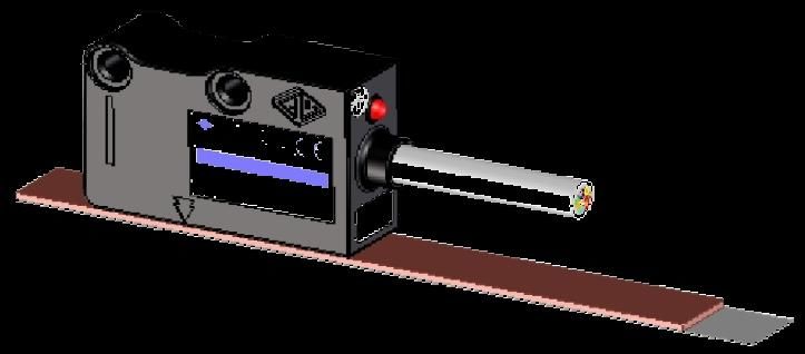
TRASDUTTORE MAGNETICO TM+MP MAGNETIC SCALE TM+MP
1. CONSIDERAZIONI PRELIMINARI 1. PRELIMINARY REMARKS
Prima di procedere all’installazione del prodotto, leggere attentamente le Before proceeding with the installation of the product, read carefully the
note riportate di seguito. following instructions.
Eseguire le connessioni in assenza di tensione di alimentazione Make connections when power supply is switched off, and batteries
escludendo anche l’alimentazione di sicurezza (batterie) nelle (when present) are excluded as well.
apparecchiature che la prevedono.
During machining, remove any accumulation of swarfs, dusts, etc. that
Nel corso delle lavorazioni rimuovere gli accumuli di trucioli, polveri, ecc. does not allow the free sliding of the movable parts.
che si oppongono al libero scorrimento delle parti mobili.
The use of a protection cover is recommended to prevent any damage
L’aggiunta di un carter (soprattutto per gli assi particolarmente esposti), from falling tools or material.
può costituire un valido riparo dalla caduta accidentale di attrezzi o
lavorati.
Assicurarsi che gli attrezzi utilizzati per il montaggio siano
rigorosamente smagnetizzati. Verify that all
demagnetized.
the tools used for mounting are strictly
2. RESISTENZA AD AGENTI CHIMICI 2. RESISTANCE TO CHEMICAL AGENTS
PRODOTTI POCO INFLUENTI LOW-IMPACT AGENTS
Acido formico, acido lattico, formaldeide 40%, glicerina 93 C, esano, Formic acid, lactic acid, formaldehyde 40%, glycerine 93 C, hexane,
iso-ottano, olio di lino, olio di semi di cotone, olio di semi di soia, olio iso-octane, linseed oil, cotton oil, soybean oil, mineral oil.
minerale.
PRODOTTI DI MEDIA INFLUENZA MEDIUM-IMPACT AGENTS
Acetilene, acetone, acido acetico, acido oleico, acido stearico 70 C, Acetylene, acetone, acetic acid, oleic acid, stearic acid 70 C, seawater,
acqua di mare, ammoniaca, benzina, etere isopropilico, petrolio, vapore. ammonia, gasoline, ether isopropyl, petroleum, vapour.
PRODOTTI DI FORTE INFLUENZA STRONG-IMPACT AGENTS
Acido nitrico, benzene, dimetilbenzene, furano tetraetile, nitrobenzene, Nitric acid, benzene, dimethylbenzene, tetraethyl furan, nitrobenzene,
solvente per vernice, toluene, tetracloruro di carbonio, trementina, solvent, toluene, carbon tetrachloride, turpentine, trichloroethylene.
trielina.
Proteggere la banda da campi magnetici esterni. Il contatto
con calamite o altri magneti permanenti può danneggiare la Protect the band from external magnetic fields. Contact with
any permanent magnet can irreparably damage the magnetic
banda magnetica in modo irreparabile. band.
3. FISSAGGIO DELLA BANDA MAGNETICA MPx00 3. FIXING OF MAGNETIC BAND MPx00
Per garantire l’accuratezza del sistema, la banda magnetica guarantee the system accuracy, the magnetic band has
deve essere più lunga di circa 80 mm rispetto alla corsa To
to be 80 mm longer than the measuring length of the machine
utile della macchina (40 mm per parte). (40 mm for each side).
Durante il montaggio, posizionare la banda magnetica During mounting, the magnetic band has to be adequately
centrandola opportunamente sulla corsa utile. centered on the measuring length.
La banda magnetica può essere applicata su qualsiasi superficie di The magnetic band can be fixed on any kind of non-magnetic surface.
materiale non magnetizzato. Per una miglior protezione della banda For a better protection of the magnetic band from shavings, liquids,
magnetica in presenza di trucioli, liquidi, polvere, ecc., è consigliabile powder, etc., we recommend the use of the protective cover CP103 ,
utilizzare il nastro di acciaio di protezione CP103 , già provvisto di already equipped with a double-sided adhesive tape , or of the
biadesivo , oppure il supporto di protezione in alluminio SP202, che aluminium support SP202 which keeps the magnetic band in the proper
mantiene in posizione la banda magnetica (si veda la figura nella pagina position (see the picture in the next page).
seguente).
La temperatura ottimale di incollaggio è compresa tra 20 °C e 30 °C. The best gluing temperature is between 20 °C and 30 °C. It is not
Si sconsiglia di eseguire l’incollaggio a temperature inferiori ai 10 °C. advisable to perform the operation at temperatures below 10 °C.
Nel caso in cui la banda magnetica sia stata immagazzinata ad una In case the magnetic band has been stocked at a lower or higher
temperatura inferiore o superiore a quella della macchina, è preferibile temperature than the machine, it is advisable to wait some hours before
attendere alcune ore per la sua stabilizzazione. L’adesione delle parti gluing it, to stabilize the magnetic band. The adhesion of glued parts is
incollate si completa dopo almeno 48 ore. completed after at least 48 hours.
Per l’incollaggio della banda magnetica, procedere come segue: To glue the magnetic band, proceed as follows:
Pulire accuratamente la superficie di fissaggio da qualsiasi traccia di Clean carefully the fixing surface from oil, grease or any kind of dirt,
olio, grasso o sporcizia, utilizzando solventi la cui evaporazione non using trace-free solvents.
lasci residui.
Sollevare di alcuni centimetri il supporto di protezione del biadesivo Raise few centimeters of the adhesive protection and place the
e posizionare opportunamente la banda magnetica, esercitando magnetic band properly, exerting a light pressure on the initial
una leggera pressione nella zona di adesione iniziale. adhesive zone.
Procedere nella stesura della banda magnetica rimuovendo
progressivamente il supporto di protezione del biadesivo ed Proceed with the magnetic band fixing, removing progressively the
esercitando una pressione uniforme. Se possibile utilizzare un piccolo adhesive protection and exerting a uniform pressure. If possible,
rullo manuale. use a small manual roller.
Procedere come sopra all’incollaggio del nastro di protezione in Proceed as above to glue the stainless steel cover tape on the
acciaio sulla superficie della banda magnetica, dopo averla magnetic band, after having accurately cleaned the surface.
accuratamente pulita.
Utilizzare il tratto eccedente del nastro di protezione per il suo Use the exceeding part of the protective cover tape for its
fissaggio meccanico ed il suo collegamento alla terra, con viti TC mechanical fixing and ground connection, by means of screws
M3x8 . M3x8 .
Pag. 2/8
Tm_Mp200.Docx rev. I
03/05/2010TRASDUTTORE MAGNETICO TM+MP MAGNETIC SCALE TM+MP
2 3
5 1
SP202
4
MP
FISSAGGIO CONSIGLIATO PER IL SUPPORTO SP202
RECOMMENDED FIXING OF SUPPORT SP202
Non è possibile utilizzare il supporto SP202 se la banda
magnetica è protetta dal cover CP103. It is not possible to use the SP202 support if the magnetic
band is already protected by the CP103 cover.
Sulla banda magnetica MP100 non è possibile applicare alcun
nastro protettivo. It is not possible to apply any protective cover on the
magnetic band MP100.
4. FISSAGGIO DELLA BANDA MAGNETICA MPx00Z 4. FIXING OF MAGNETIC BAND MPx00Z
La banda magnetica MP200Z / MP500Z (con impulsi di zero in posizioni The magnetic band MP200Z / MP500Z (with zero references positioned
a richiesta, solo per TM xxxZ / HxxxZ), deve essere fissata alla macchina upon request, only for TM xxxZ / HxxxZ), must be fixed to the machine
come le altre bande magnetiche seguendo le indicazioni riportate nel as the other magnetic bands following the indications provided in
paragrafo 3. paragraph 3.
Per la definizione delle posizioni di zero, sensore e banda
magnetica sono da considerare orientati come nel disegno For the definition of the zero reference position, the sensor
and the magnetic band have to be considered oriented as in
seguente. the following drawing.
TM MxxxZ / TM HxxxZ
MP200Z / MP500Z
ESEMPIO: MP200Z / MP500Z con impulsi di zero
a 60 mm e 80 mm da sinistra. MP200Z/MP500Z IMPULSO DI ZERO SU BANDA MAGNETICA
MP200Z/MP500Z ZERO REFERENCE ON MAGNETIC BAND
EXAMPLE: MP200Z / MP500Z with zero references
at 60 mm and 80 mm from the left.
ORIENTAMENTO MP200Z / MP500Z – MP200Z / MP500Z ORIENTATION
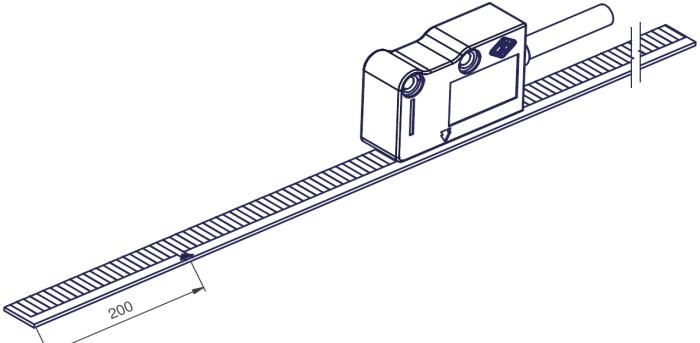
5. MONTAGGIO DEL SENSORE TM 5. TM SENSOR MOUNTING
Procedere al fissaggio del sensore magnetico utilizzando i due fori Use the two M4 threaded holes to fix the magnetic sensor. As an
filettati M4. In alternativa, considerarli come fori passanti per viti TCEI alternative, they can be used as through holes for TCEI M3x18 screws.
M3x18. The sensor can be mounted in any position, keeping the active side,
Il sensore può essere montato in qualsiasi posizione mantenendo il lato marked by arrows, towards the surface of the magnetic band.
attivo, indicato dalle frecce, verso la superficie della banda magnetica. Once the mechanical mounting has been concluded, manually cover the
Una volta concluso il montaggio meccanico, compiere manualmente la entire measuring length to make sure that both the sensor and the cable
corsa totale per accertarsi che nulla si opponga al libero scorrimento are able to move without interferences.
delle parti mobili. Check the respect of the alignment tolerances and the distance between
Controllare il rispetto delle tolleranze di allineamento del sensore e la sensor and magnetic band along the entire measuring length. Any
sua distanza, rispetto alla banda magnetica, lungo tutta la corsa. Ogni positioning error must be corrected.
errore di posizione deve essere corretto. Spacer blocks or supporting arms should be adequately sized and made
Eventuali squadrette o bracci di supporto vanno opportunamente rigid to exclude any flexion or vibration that could compromise the
dimensionati e resi rigidi, in maniera tale da escludere qualsiasi loro system’s accuracy.
flessione o vibrazione che possa compromettere la precisione del
sistema.
Pag. 3/8
Tm_Mp200.Docx rev. I
03/05/2010TRASDUTTORE MAGNETICO TM+MP MAGNETIC SCALE TM+MP
DIMENSIONI E SCHEMA DI FORATURA – DIMENSIONS AND DRILLING DIAGRAM
valori in mm MPx00 MPx00
MPx00
values in mm + CP103 + SP202
s 1,3 1,6 2,1
d TM P 0,1 0,5 N.A. N.A.
d TM 0,3 1,5 1,2MAX 0,7MAX
d TM H 0,3 3,5 3,2MAX 2,7MAX
s = spessore / thickness
d = distanza da mantenere tra sensore e superficie del nastro magnetico (o dell’eventuale cover/supporto)
distance to be maintained between sensor and surface of the magnetic band (or eventual cover/support)
TOLLERANZE DI ALLINEAMENTO – ALIGNMENT TOLERANCES
a
TM XxxxC
a TM XxxxE
TM XxxxZ
a (mm) 3MAX 1MAX
a= tolleranza di allineamento
alignment tolerance
6. MONTAGGIO RIFERIMENTO DI ZERO ESTERNO 6. EXTERNAL ZERO REFERENCE MOUNTING
Per il montaggio del riferimento di zero esterno, procedere come segue: For the installation of the external zero reference (magnet) proceed as
Sensore e banda magnetica devono essere già fissati alla macchina follows:
nella loro posizione definitiva. Both the sensor and the magnetic band have to be previously fixed
Portare il sensore sul punto in cui si vuole avere la posizione di zero to the machine, in their final position.
e spostarsi nell’intorno di alcuni millimetri sino all’accensione del led Place the sensor where the zero position is needed and move it
rosso di index. around some millimeters until the index red led turns on.
Posizionare la base del riferimento esterno parallelamente alla banda Place the base of the reference parallel to the magnetic band, at a
magnetica, ad una distanza D dal sensore (si veda il disegno distance D from the sensor (see following drawing). Make the notch,
seguente). Far coincidere la tacca presente sulla parte superiore del located on the upper part of the reference, correspond to the vertical
riferimento, con quella verticale del corpo esterno del sensore. one on the body of the sensor.
Segnare sulla macchina la posizione dei fori M3 per il fissaggio del On the machine, mark the position of M3 holes for fixing the
riferimento. reference.
Eseguire i fori di fissaggio e bloccare il riferimento con 2 viti TC Drill the fixing holes and tighten the reference by 2 socket head
M3x12, tenendo la parte attiva (magneti) verso il sensore. I fori screws M3x12, keeping the active part (magnets) toward the sensor.
asolati consentono uno spostamento lungo l’asse della banda The slots permit a displacement on the magnetic band axis, in order
magnetica per un posizionamento preciso del riferimento. to get an accurate positioning of the reference.
Effettuare una prova di funzionamento in entrambi i sensi di Test the proper functioning in both directions of motion.
avanzamento.
Non
alla
appoggiare o avvicinare eccessivamente il riferimento
banda magnetica in quanto i magneti contenuti Do not put the reference in contact or too close to the
magnetic band, since the internal magnets could irreparably
potrebbero danneggiarla irrimediabilmente. damage it.
Pag. 4/8
Tm_Mp200.Docx rev. I
03/05/2010TRASDUTTORE MAGNETICO TM+MP MAGNETIC SCALE TM+MP
RIFERIMENTO DI ZERO ESTERNO – EXTERNAL ZERO REFERENCE
INDICI DI RIFERIMENTO
D (mm) REFERENCE INDEXES
TM P (MP100) N.A. N.A.
TM (MP200) 1,5TYP 2MAX
D
TM H (MP500) 1TYP 2MAX
7. SEGNALI D’USCITA 7. OUTPUT SIGNALS
LINE DRIVER PUSH-PULL
A
A
A
B
B
B
I0 I0
I0 90° 180° 270° 360°
90° 180° 270° 360°
8. CAVI E COLLEGAMENTI ELETTRICI 8. CABLES AND ELECTRICAL CONNECTIONS
La riga magnetica TM+MP viene fornita con cavo 8 poli = 5,8 mm. TM+MP magnetic scale is supplied with a 8-wire cable = 5.8 mm.
NOTA. NOTE.
Rispettare un raggio minimo di curvatura del cavo di 60 mm. The cable’s bending radius should not be lower than 60 mm.
Sono disponibili in uscita i seguenti segnali: The following output signals are available:
COLORE CONDUCTOR
SEGNALI SIGNALS
CONDUTTORE COLOR
A Verde A Green
A Arancio A Orange
B Bianco B White
B Azzurro B Light-blue
I0 Marrone I0 Brown
I0 Giallo I0 Yellow
V+ Rosso V+ Red
V- Blu V- Blue
SCH Schermo SCH Shield
Il sensore ha una configurazione di uscita LINE DRIVER. Se The sensor is set up with a LINE DRIVER output. If the reading device
l’apparecchiatura di lettura non è predisposta per la lettura di segnali in cannot read complementary signals, it is necessary to isolate the unused
differenziale, è necessario isolare singolarmente i conduttori non wires one by one. It is important to note that the connection of the
utilizzati. E’ importante considerare che il collegamento dei conduttori unused wires can damage the sensor and it does not guarantee its
non utilizzati può provocare il danneggiamento del sensore e non immunity from interferences.
garantisce l’immunità ai disturbi. Avoid locating the cable next to any device that may cause
Evitare di eseguire percorsi del cavo prossimi a dispositivi che possano electromagnetic interferences (motors, solenoid valves, inverters).
essere fonte di disturbi elettromagnetici (motori, elettrovalvole, inverter).
If interferences are detected, act directly on the source of disturb using
Qualora si rilevassero interferenze, intervenire direttamente sulla
EMC filters.
sorgente del disturbo utilizzando allo scopo opportuni filtri EMC.
Pag. 5/8
Tm_Mp200.Docx rev. I
03/05/2010TRASDUTTORE MAGNETICO TM+MP MAGNETIC SCALE TM+MP
Per l’esecuzione di prolunghe è indispensabile l’utilizzo di cavi If cable extensions are needed, it is necessary to use shielded cables
schermati con sezione minima di 0,5 mm 2 per le alimentazioni e with a section of at least 0.5 mm2 for power supply and 0.14 mm2 for
0,14 mm2 per i segnali. signals.
Verificare il corretto collegamento e la continuità dello schermo elettrico Verify the correct connection and the continuity of the shield which has
che deve essere collegato ad un nodo di messa a terra avente minima to be connected to an earthing node with minimum impedance ( 0 ).
impedenza ( 0 ).
The sensor is supplied with a standard 2 m-long cable. Longer lengths
Il sensore è fornito di serie con un cavo di lunghezza standard 2 m. Si
can be required, considering the following maximum values:
possono richiedere cavi di lunghezza superiore, tenendo conto delle
seguenti lunghezze massime possibili: LMAX = 10 m (sensor cable);
LMAX = 100 m (2 m sensor cable + cable extension).
LMAX = 10 m (cavo sensore);
LMAX = 100 m (2 m cavo sensore + prolunga). To balance LINE DRIVER output, the following resistance loads have to
Il carico resistivo per bilanciare l’uscita LINE DRIVER, dovrà essere: be used:
5V RL = 120 5V RL = 120
12V RL = 1.2 k 12V RL = 1.2 k
24V RL = 1.2 k 24V RL = 1.2 k
Per applicazioni dove la velocità massima è superiore a 1 m/s, è For applications where the maximum speed exceeds 1 m/s, the use of a
indispensabile l’uso di un cavo speciale adatto alla posa mobile. special cable, suitable to continuous movements, is required.
In caso di prolunga, garantire il collegamento elettrico tra il
corpo dei connettori e lo schermo dei cavi. In case of cable extension, the electrical connection between the
body of the connectors and the cables shield must be ensured.
9. USO E MANUTENZIONE 9. USE AND MAINTENANCE
La banda magnetica e il sensore TM+MP non necessitano di alcuna The magnetic band and the TM+MP sensor do not require any particular
particolare manutenzione. L’installazione dei prodotti conforme alle maintenance. A proper installation, complying to the mounting
istruzioni di montaggio ed il loro corretto utilizzo costituiscono fattori di instructions, and the correct use guarantee quality and good operation.
stabilità qualitativa.
Any discrepancy should be reported to the Manufacturer for repairing or
In caso di anomalie di funzionamento consultare la Casa Costruttrice replacement of defective parts.
per la riparazione o sostituzione di parti difettose.
After maintenance, verify the mounting tolerances and adjust any
Verificare le tolleranze di montaggio ed il corretto allineamento del
eventual misalignment.
sistema al termine di qualsiasi intervento che possa averlo modificato.
Per non compromettere la precisione del sistema di misura, evitare di To preserve the accuracy of the system, do not stress mechanically the
stressare meccanicamente la banda magnetica. Questa deve sempre magnetic band. The band has to be rolled always in the same way
essere avvolta nello stesso senso (nastro di plastoferrite rivolto verso (plastoferrite towards the outside), with a minimum diameter of 260 mm.
l’esterno), con un diametro non inferiore a 260 mm.
10. TERMINI DI GARANZIA 10. WARRANTY TERMS
Il sensore TM+MP è garantito esente da difetti di fabbricazione per un periodo di TM+MP sensor is guaranteed against manufacturing faults for a period of twelve
dodici mesi dalla data di acquisto. L’eventuale riparazione dovrà essere effettuata months from the date of purchase. Any repair must take place at the Manufacturer’s
presso la Casa Costruttrice e il Cliente sarà tenuto a provvedere alla consegna del premises and the Customer shall arrange the delivery of the product, at its own risk
prodotto presso la stessa. and expense.
L’inosservanza delle istruzioni e tolleranze di montaggio determina il decadimento The Manufacturer is released from any claim against damages due to the non-
dei termini di garanzia ed esonera la Casa Costruttrice dal rispondere dei observance of these instructions or mounting tolerances which causes the annulment
malfunzionamenti causati da installazioni non conformi. of the warranty terms.
La Casa Costruttrice non sarà tenuta a riparare e/o sostituire in garanzia tutte le The warranty does not provide for repairing and/or replacement of those parts that
parti che dovessero risultare difettose a causa di negligenza o trascuratezza have been damaged by negligence or misuse, improper installation or maintenance,
nell’uso, di errata installazione o manutenzione, di manutenzioni operate da maintenance performed by unauthorized personnel, transport or any other
personale non autorizzato, di danni derivanti dal trasporto, ovvero di circostanze che circumstance that excludes a manufacturing fault of the product.
non è possibile far risalire a difetti di fabbricazione dell’apparecchio. Similarly, the warranty does not apply if serial numbers or any data identifying the
La garanzia è altresì esclusa qualora vengano cancellati o alterati i numeri di product are cancelled or altered in any way, and if product modifications are
matricola o i dati identificativi del prodotto, e qualora vengano apportate modifiche introduced without the written authorization of the Manufacturer.
senza il consenso scritto della Casa Costruttrice.
La Casa Costruttrice declina ogni responsabilità per eventuali danni a cose o a The Manufacturer declines any responsibility for damages to people or properties
persone derivanti dall’utilizzo del prodotto, inclusa, senza limitazione, qualsiasi deriving from the use of the product, including any loss of profit or any other direct,
perdita di guadagno ed ogni altra perdita anche indiretta o incidentale. indirect or incidental loss.
11. SMALTIMENTO 11. DISPOSAL
Direttiva sui rifiuti di apparecchiature elettriche ed elettroniche (RAEE) Disposal of waste electrical and electronic equipment (WEEE)
Direttiva 2002/96/CE del Parlamento Europeo European Council Directive (2002/96/EC)
Il simbolo RAEE utilizzato per questo dispositivo indica che The use of the WEEE Symbol indicates that this product may not be
quest'ultimo non può essere trattato come rifiuto domestico. treated as household waste.
Lo smaltimento corretto di questo prodotto contribuirà a If this product is disposed correctly, you will help to protect the
proteggere l'ambiente. environment.
Per maggiori informazioni sul riciclaggio di questo apparecchio,
For more detailed information about the recycling of this product,
rivolgersi all'ufficio competente del proprio ente locale, alla please contact your local authority, your household waste disposal
società addetta allo smaltimento dei rifiuti domestici o al service provider or the retailer where you purchased the product.
rivenditore.
Questa informativa riguarda unicamente i clienti europei in This information regards only European customers, according to
conformità con la Direttiva del Parlamento europeo n. 2002/96/EC European Parliament Directive.
2002/96/CE. Per gli altri Paesi, fare riferimento alle Leggi locali. For other countries, please refer to local law requirements.
Pag. 6/8
Tm_Mp200.Docx rev. I
03/05/2010TRASDUTTORE MAGNETICO TM+MP MAGNETIC SCALE TM+MP
12. CARATTERISTICHE TECNICHE – TM+MP 12. TECHNICAL FEATURES – TM+MP
CARATTERISTICHE GENERALI GENERAL CHARACTERISTICS
Ripetibilità 1 incremento Repeatability 1 increment
LINE DRIVER Output LINE DRIVER
Uscita
PUSH-PULL PUSH-PULL
Frequenza massima 300 kHz Maximum frequency 300 kHz
Alimentazione 5 28 Vdc ± 5% Power supply 5 28 Vdc ± 5%
140 mAMAX (con 5V e RL = 120 ) 140 mAMAX (with 5V and RL = 120 )
Assorbimento con carico Current consumption with load
90 mAMAX (con 28V e RL = 1.2 k ) 90 mAMAX (with 28V and RL = 1.2 k )
Sfasamento 90° ± 5° elettrici Phase displacement 90° ± 5° electrical
Resistenza a vibrazioni (EN60068-2-6) 300 m/s2 [55 ÷ 2000 Hz] Vibration resistance (EN60068-2-6) 300 m/s2 [55 ÷ 2000 Hz]
2 2
Resistenza agli urti (EN 60068-2-27) 1000 m/s (11 ms) Shock resistance (EN 60068-2-27) 1000 m/s (11 ms)
Grado di protezione (EN 60529) IP 67 Protection class (EN 60529) IP 67
Temperatura di esercizio 0 °C ÷ 50 °C Operating temperature 0 °C ÷ 50 °C
Temperatura di stoccaggio -20 °C ÷ 80 °C Storage temperature -20 °C ÷ 80 °C
Umidità relativa 100% Relative humidity 100%
Peso 40 g Weight 40 g
Protezioni elettriche inversione di polarità e cortocircuiti Electrical protections inversion of polarity and short circuits
SENSORE TM P SENSOR TM P
Impulso di zero passo costante ogni 1 mm (C) Zero reference constant pitch every 1 mm (C)
Passo polare 1+1 mm Pole pitch 1+1 mm
Risoluzione 10 - 5 - 1 - 0,5 μm Resolution 10 - 5 - 1 - 0.5 μm
Accuratezza * ± 10 μm Accuracy * ± 10 μm
Velocità max. di traslazione 0,6 m/s (MTS P05) 1,2 m/s (MTS P1) Max. traversing speed 0.6 m/s (MTS P05) 1.2 m/s (MTS P1)
SENSORE TM SENSOR TM
passo costante ogni 2 mm (C) constant pitch every 2 mm (C)
Impulso di zero esterno (E) Zero reference external (E)
posizionato su banda magnetica (Z) positioned on magnetic band (Z)
Passo polare 2+2 mm Pole pitch 2+2 mm
Risoluzione 1000 - 500 - 100 - 50 - 25 - 10 - 5 - 1 μm Resolution 1000 - 500 - 100 - 50 - 25 - 10 - 5 - 1 μm
Accuratezza * ± 15 μm Accuracy * ± 15 μm
Velocità max. di traslazione 1,2 m/s (TM 1) 12 m/s (TM 10) Max. traversing speed 1.2 m/s (TM 1) 12 m/s (TM 10)
SENSORE TM H SENSOR TM H
passo costante ogni 5 mm (C) constant pitch every 5 mm (C)
Impulso di zero esterno (E) Zero reference external (E)
posizionato su banda magnetica (Z) positioned on magnetic band (Z)
Passo polare 5+5 mm Pole pitch 5+5 mm
Risoluzione 100 - 50 - 25 - 10 - 5 μm Resolution 100 - 50 - 25 - 10 - 5 μm
Accuratezza * ± 40 μm Accuracy * ± 40 μm
Velocità max. di traslazione 6 m/s (TM H5) 12 m/s (TM H10) Max. traversing speed 6 m/s (TM H5) 12 m/s (TM H10)
* Il valore dichiarato è subordinato al rispetto delle tolleranze di allineamento prescritte dalla * To reach the declared value it is necessary to respect the alignment tolerances prescribed by
Casa Costruttrice e può essere migliorato riducendo la distanza tra il sensore e la banda the Manufacturer. Better accuracies can be obtained by reducing the gap between the sensor
magnetica. and the magnetic band.
13. CARATTERISTICHE TECNICHE – BANDA MP 13. TECHNICAL FEATURES – BAND MP
MP100 MP200 (Z) MP500 (Z) MP100 MP200 (Z) MP500 (Z)
Passo polare 1+1 2+2 5+5 Pole pitch 1+1 2+2 5+5
± 30 μm/m standard ± 30 μm/m standard
Accuratezza a 20 C Accuracy at 20 C
± 15 μm/m speciale ± 15 μm/m special
Larghezza 10 mm Width 10 mm
Spessore 1,3 mm Thickness 1.3 mm
Lunghezza massima * 50 m 50 m 25 m Maximum length * 50 m 50 m 25 m
Dilatazione termica 10,6 x 10⁻⁶ °C-1 T rif. = 20 °C ± 0,1 °C Thermal expansion 10.6 x 10⁻⁶ °C-1 T ref. = 20 °C ± 0.1 °C
Raggio di curvatura 130 mmMIN Bending radius 130 mmMIN
Temperatura di esercizio 0 °C ÷ 70 °C Operating temperature 0 °C ÷ 70 °C
Temperatura di stoccaggio -20 °C ÷ 80 °C Storage temperature -20 °C ÷ 80 °C
Peso banda magnetica 65 g/m Magnetic band weight 65 g/m
Peso nastro protezione 25 g/m Cover weight 25 g/m
* Per la versione special accuracy, lunghezza massima 20 m. * For the special accuracy version, maximum length 20 m.
Senza obbligo di preavviso, i prodotti potrebbero essere soggetti a Without prior notice, the products may be subject to modifications
modifiche che la Casa Costruttrice si riserva di apportare perché
ritenute necessarie al miglioramento degli stessi.
that the Manufacturer reserves to introduce as deemed necessary
for their improvement.
Pag. 7/8
Tm_Mp200.Docx rev. I
03/05/2010ELAP VIA VITTORIO VENETO, 4 – I-20094 CORSICO (MI) TEL. ++39.02.4519561
FAX ++39.02.45103406 E-MAIL: INFO@ELAP.IT SITE: WWW.ELAP.ITPuoi anche leggere