THE CEMENT-BENTONITE DIAPHRAGM OF THE MALAGROTTA MUNICIPAL WASTE LANDFILL (ROME, ITALY): EFFICIENCY ANALYSIS
←
→
Trascrizione del contenuto della pagina
Se il tuo browser non visualizza correttamente la pagina, ti preghiamo di leggere il contenuto della pagina quaggiù
DOI: 10.4408/IJEGE.2021-02.O-05

THE CEMENT-BENTONITE DIAPHRAGM OF THE MALAGROTTA MUNICIPAL
       WASTE LANDFILL (ROME, ITALY): EFFICIENCY ANALYSIS

                                              Franco BRAGA(*) & Alberto PRESTININZI(**)
                  (*)
                      Former Professor of construction technique and construction in seismic areas - Sapienza University of Rome - Rome (Italy)
     (**)
            Former Professor of geological risks - Sapienza University of Rome, Honorary president of the Nhazca start-up - Sapienza University of Rome,
                    Professor of risk analysis - eCampus University, School of engineering - Via Isimbardi, 10 - 22060 Novedrate (Como, Italy)
                                                     Corresponding author: alberto.prestininizi@uniroma1.it

EXTENDED ABSTRACT
    La discarica di Rifiuti Solidi Urbani (RSU) della Città di Roma, una delle più estese d’Europa, nasce nell’area di Malagrotta
dove erano presenti, tra gli anni ‘50 e i primi del 1960, importanti attività di estrazione di sabbia e ghiaia utilizzate come inerti nelle
costruzioni, destinate alla rapida espansione urbana della Città di Roma del dopoguerra, ma anche alla realizzazione di importanti
infrastrutture come le piste dell’Aeroporto Leonardo da Vinci di Fiumicino (Roma). La complessa stratigrafia dell’area, schematiz-
zata, dall’alto verso il basso, è caratterizzata dalla presenza di depositi vulcanici, sabbie e ghiaie. Questi depositi si trovano al di
sopra della importante formazione geologica delle argille grigio-azzurre di età Plio-pleistocenica, ad elevata consistenza e bassa
permeabilità (Carboni, 1980). Lo spessore delle argille grigio-azzurre è molto importante e presenta, nell’area di indagine, valori
non inferiori ai 100 metri. Il contatto con le soprastanti sabbie e ghiaie è molto irregolare e si sviluppa su una superficie trasgressiva.
Lo spessore delle ghiaie, pertanto, varia da pochi metri fino a decine di metri (Galeotti et alii, 1990; Carboni, 1980). E’ in questo
ambiente geologico che lo smaltimento dei Rifiuti Solidi Urbani ha trovato le condizioni ideali, grazie alla presenza di molte cavità,
ereditate dall’asporto di grandi quantità di materiali inerti per un volume stimato, nel 1987, in oltre 200 × 106 m3.
    A seguito del Decreto del Presidente della Repubblica (DPR) 915/82 del 10 settembre 1982, emanato in accoglimento di tre
Direttive europee, fra le quali la Direttiva 75/442/CEE del Consiglio, del 15 luglio 1975, relativa ai rifiuti, la discarica è stata sot-
toposta a interventi di bonifica e di messa in sicurezza. L’intervento più importane di adeguamento alle nuove normative, dal punto
di vista sia economico sia tecnico-scientifico, è rappresentato dall’isolamento idraulico dell’area destinata a discarica, costituito da
un diaframma cemento-bentonite fondato a profondità variabile (Fig. 1, 2, 3) e ammorsato per oltre due metri nelle argille grigio-
azzurre sovraconsolidate di base. Le miscele di cemento-bentonite, utilizzate per costruire diaframmi plastici, costituiscono materiali
speciali che hanno il fondamentale obiettivo della protezione di particolari siti, dovendo fornire prestazioni caratterizzate da bassa
conducibilità idraulica e, allo stesso tempo, da elevati valori di resistenza e buon comportamento elastico. Il comportamento, soprat-
tutto idraulico di queste miscele, è stato ampiamente studiato in laboratorio e in sito (Vespo et alii, 2021). Escludendo i diaframmi
che hanno la parte sommitale emergente al di sopra del piano campagna, con conseguente esposizione di una porzione dell’opera agli
agenti atmosferici (Jefferis, 1981; Opukumo et alii, 2021; Grisolia et alii, 2000), meno frequenti sono gli studi e le ricerche orien-
tate a verificare lo stato di conservazione e di efficienza idro-meccanica nel tempo dei diaframmi plastici che si trovano interamente
posizionati al di sotto del piano campagna. Nella presente nota, è stato esaminato il caso del diaframma plastico realizzato nell’area
di Malagrotta (Roma, Italia), tra settembre 1988 e novembre 1989, con l’obiettivo di confinare i Rifiuti Solidi Urbani provenienti,
per lo più, dalla città di Roma (Italia). Verificare il suo livello di efficienza è ora opportuno, specie a causa delle indagini giudiziarie
che ipotizzano una perdita di efficienza di questa importante opera, in termini di conducibilità idraulica e comportamento elastico.
    Per fare chiarezza al riguardo sono stati utilizzati i dati disponibili, ricavati da una serie di test idraulici effettuati nel sito di
Malagrotta in prossimità del perimetro del diaframma plastico. E’ stato possibile valutare le condizioni di flusso idraulico e gli
spostamenti elastici teorici del diaframma (freccia e area della deformata) corrispondenti alle variazioni di carico. I risultati ottenuti
sono stati analizzati attraverso l’equazione della linea elastica, utilizzando anche i dati contenuti nel progetto del diaframma plastico
(Calenda & Esu, 1988). Dal confronto tra questi dati sperimentali e i risultati ottenuti dalle valutazioni analitiche, elaborati anche
attraverso confronti statistici, sono emersi dati complessivamente tranquillizzanti che segnalano un eccellente stato di conservazione
dell’opera e della sua efficienza, ad oltre 34 anni dalla sua realizzazione.

Italian Journal of Engineering Geology and Environment, 2 (2021)          © Sapienza Università Editrice                               www.ijege.uniroma1.it   51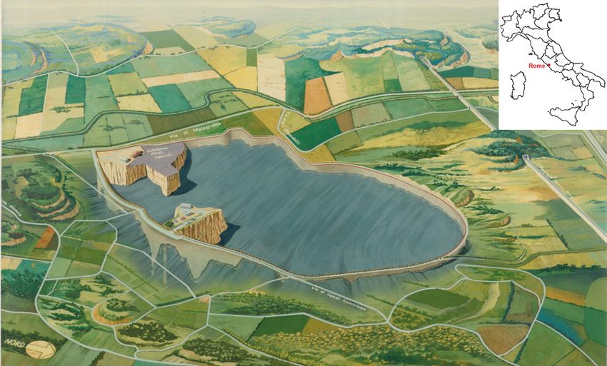
F. BRAGA & A. PRESTININZI

     ABSTRACT                                                                       of a cement-bentonite mixture. The results of the application
          The MSW landfill of the city of Rome, one of the largest                  of the equations of the elastic line revealed that the undrained
     in Europe, was created in the area of Malagrotta. Between the                  behaviour of the soil-diaphragm system was in line with our
     1950s and the early 1960s, this area hosted important sand and                 analyses based on experimental data from hydraulic tests and
     gravel quarries, which supplied aggregates for construction                    statistical tests.
     projects, such as those necessary for the rapid urban expansion                    By using Equations (3) and (4), we computed the values
     of Rome after the second world war.                                            umax and Aumax for all the time steps ti. Statistical processing
          The area has a complex stratigraphy, schematically                        of the data enabled us to compare all the available results:
     consisting (from top to bottom) of volcanic deposits, sands,                   piezometric heads in V7, piezometric heads induced in Z7,
     gravels, and very compact gray-blue clays.                                     arrow umax (x = 0), and surface area Aumax acting on the
          This geological setting, with cavities from the previous                  diaphragm. In particular, the comparison highlighted their
     quarrying of large volumes of aggregates (estimated at over                    mutual relationships under the various conditions of stress q,
     200 × 106 m3 in 1987), offered an ideal site for MSW disposal.                 thereby validating the linear proportionality of the diaphragm
          Remediation and safe confinement projects were                            displacement and the origin of the piezometric changes
     undertaken at the landfill site after the issuing of Decree of                 ΔHZ7. Indeed, the data of Tables 2 and 3 shows the linear
     the President of the Republic 915/82 of 10 September 1982,                     proportionality of ratios (V7/Z7) and of changes in hydraulic
     transposing three European Directives, including Council                       head with the data connected with the diaphragm displacement,
     Directive 75/442/EEC of 15 July 1975 on waste, into the                        ΔH(Z7)/[(Au)/(umax (x = 0)].
     Italian legislation. From a financial and technical-scientific                     The analysis of these results confirmed what we had
     viewpoint, the most important project to make the landfill                     observed during hydraulic investigations: the behaviour of the
     compliant with the new legislation was the construction of                     system, subjected to hydraulic stress tests, proved to be typical
     a hydraulic sealing wall around the internal subareas of the                   of undrained systems, which respond to stress changes with
     landfill that would accommodate MSW. The wall consisted in                     exchanges of energy and induced deformations at constant
     a plastic diaphragm of variable depth (Fig. 1).                                volume (Figs. 3, 5, 6 a) and b)).
          This is one of the major barrier walls built in the world for                 After more than 34 years since its construction, the
     the confinement of MSW landfills (Table 1).                                    cement-bentonite plastic diaphragm retains an excellent
          As part of the activities undertaken at the Malagrotta                    hydromechanical efficiency, allowing it to perform its
     landfill site, we investigated the functional efficiency of                    hydraulic sealing and mechanical elastic behaviour function
     the diaphragm. Several in situ tests were thus planned and                     in the future.
     implemented. This paper analyses the results of hydraulic
     stress tests carried out in appropriate sections, provided with                Keywords: Municipal solid waste, cement-bentonite diaphragm, elastic
     piezometers and other measuring instruments making part of                     behaviour, plastic diaphragm
     the system for monitoring the entire surface area of the landfill
     (161 ha).                                                                      INTRODUCTION
          Figure 3 is a sketch of the section used for hydraulic tests,                 Cement-bentonite mixtures are special materials that are
     representing the entire confinement system (Fig. 2).                           employed to build plastic diaphragms. Their chief purpose is to
          The entire set of data confirms the efficiency of the                     protect specific sites, thanks to their low hydraulic conductivity
     confinement system examined.                                                   and high strength values and good elastic behaviour. Extensive
          The results obtained, by imposing Darcy’s solution based                  laboratory and field studies have been focused on the hydraulic
     on a reductio ad absurdum argument, demonstrates that the                      behaviour of these mixtures. However, apart from diaphragms
     cement-bentonite diaphragm is totally “impermeable” and                        with their top protruding above ground level and thus exposed
     thus fully suitable for performing the function for which it                   to weather agents (Jefferis, 1981; Opukumo et alii, 2021;
     was designed and built (Prestininzi & Romagnoli, 1991).                        Vespo et alii, 2021; Grisolia et alii, 2000), diaphragms lying
     The data shown in Table 2 corroborates this assumption,                        entirely below ground have been less frequently investigated
     i.e. the hydraulic heads in V7 and in Z7 are linked by a linear                in terms of assessment of their long-term hydraulic and
     proportionality ratio, connected with a transfer of energy                     mechanical efficiency.
     (pressure).                                                                        This paper deals with a plastic diaphragm that was built
          The findings from our hydrogeological analysis and the                    in the area of Malagrotta (Rome, Italy) between September
     application of Darcy’s law were validated by a mechanical                      1986 and November 1987, with a view to confining Municipal
     analysis of the elastic behaviour of the diaphragm, made up                    Solid Waste (MSW), mostly originating from the city of

52   Italian Journal of Engineering Geology and Environment, 2 (2021)   © Sapienza Università Editrice                              www.ijege.uniroma1.it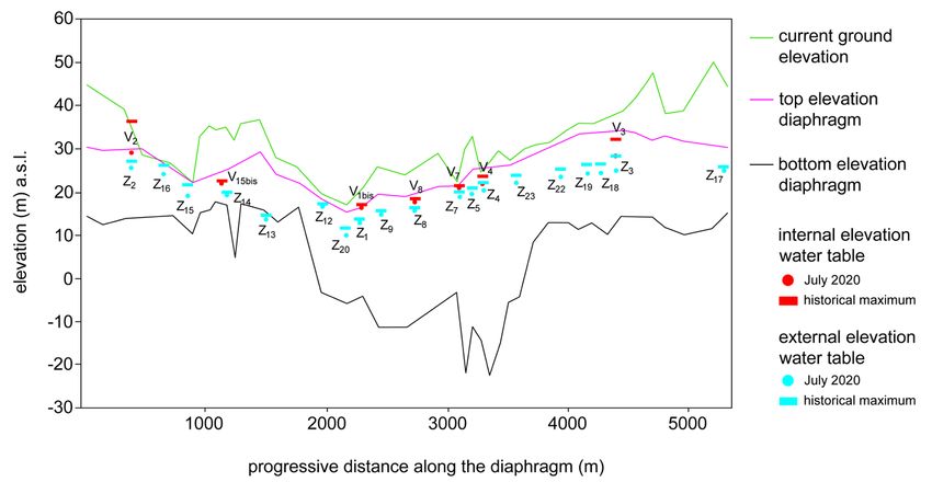
THE CEMENT-BENTONITE DIAPHRAGM OF THE MALAGROTTA MUNICIPAL WASTE LANDFILL (ROME, ITALY): EFFICIENCY ANALYSIS

Fig. 1 -   Malagrotta landfill. Perspective view of the plastic diaphragm. Eastern part of the area: trend of the top of the basal clays and configuration
           of the plastic diaphragm (modified from: Roma Capitale, 2017)

Fig. 2 -   Contact between the diaphragm and the basal clays. The figure also shows the internal (V) and external (Z) monitoring piezometers, the
           topographic surface, and the top of the diaphragm. Elevations above sea level (a.s.l.) plotted against distances measured along the perimeter
           of the diaphragm

Tab. 1 -   Geometric and structural features of the diaphragm. Construction time: 2 years.(From, Calenda & Esu, 1988)

Rome. Assessing the level of efficiency of this important                         the plastic diaphragm (Calenda & Esu, 1988). A comparison
structure has become imperative, considering the current                          between this experimental data and the findings from our
judicial investigations over its alleged loss of efficiency in                    theoretical assessments, processed with statistical methods,
terms of hydraulic conductivity and elastic behaviour. To                         yielded an overall reassuring picture, i.e. the excellent
gain an improved understanding of the issue, use was made                         hydromechanical efficiency of the structure after more than 34
of data available from a set of previous hydraulic tests carried                  years since its construction.
out at the Malagrotta site, along the perimeter of the plastic
diaphragm. Hydraulic flow conditions and theoretical elastic                      THE MALAGROTTA LANDFILL
displacements of the diaphragm were thus assessed (arrow and                          The MSW landfill of the city of Rome, one of the largest
surface area of the deformed shape). Results were analysed                        in Europe, was created in the area of Malagrotta. Between the
via both the equation of the elastic line and the design data of                  1950s and the early 1960s, this area hosted important sand and

Italian Journal of Engineering Geology and Environment, 2 (2021)      © Sapienza Università Editrice                                www.ijege.uniroma1.it    53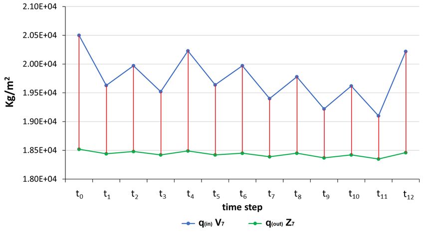
F. BRAGA & A. PRESTININZI

     gravel quarries, which supplied aggregates for construction                       Italian legislation. From a financial and technical-scientific
     projects, such as those necessary for the rapid urban                             viewpoint, the most important project to make the landfill
     expansion of Rome after the second world war, and for major                       compliant with the new legislation was the construction of
     infrastructure, e.g. the runways of Leonardo da Vinci airport                     a hydraulic sealing wall around the internal subareas of the
     at Fiumicino (Rome). The area has a complex stratigraphy,                         landfill that would accommodate MSW. The wall consisted in
     schematically consisting (from top to bottom) of volcanic                         a plastic diaphragm of variable depth (Fig. 1). The diaphragm
     deposits, sands, gravels, and very compact gray-blue clays.                       thus intersected the underlying gray-blue clays at different
     These clays of Plio-Pleistocene age belong to a significant                       depths (Fig. 2). For construction of the diaphragm, use was
     geological formation and, in the local stratigraphic succession,                  made of a hydraulic cement-bentonite mixture. This is one of
     they were assumed to be the basic lithology. Their thickness                      the major barrier walls built in the world for the confinement
     is considerable and, in the area investigated, it exceeds 100                     of MSW landfills (Table 1).
     m. Their contact with the overlying sands and gravels occurs
     at depths ranging from a few to tens of metres from ground                        HYDRAULIC CONDITIONS
     level (Galeotti et alii, 1990; Carboni, 1980). This geological                         As part of the activities undertaken at the Malagrotta landfill
     setting, with cavities from the previous quarrying of large                       site, we investigated the functional efficiency of the diaphragm.
     volumes of aggregates (estimated at over 200 × 106 m3 in                          Several in situ tests were thus planned and implemented. This
     1987), offered an ideal site for MSW disposal.                                    paper analyses the results of hydraulic stress tests carried
         Remediation and safe confinement projects were                                out in appropriate sections, provided with piezometers and
     undertaken at the landfill site after the issuing of Decree of                    other measuring instruments making part of the system for
     the President of the Republic 915/82 of 10 September 1982,                        monitoring the entire surface area of the landfill (161 ha). As
     transposing three European Directives, including Council                          pointed out about, this area is confined by a cement-bentonite
     Directive 75/442/EEC of 15 July 1975 on waste, into the                           plastic diaphragm. The resulting data was integrated with data
                                                                                       acquired from:
                                                                                            •    studies for the construction of the plastic diaphragm
                                                                                                 (Calenda & Esu, 1988);
                                                                                            •    specific scientific literature (Galeotti et alii, 1990;
                                                                                                 Grisolia et alii, 2000);
                                                                                            •    the Malagrotta area characterisation plan (Piano di
                                                                                                 Caratterizzazione della Discarica di Malagrotta, Roma
                                                                                                 Capitale, 2017);
                                                                                            •    from an archival data record built over time through
                                                                                                 surveys and analyses, but also through daily data
                                                                                                 collected from monitoring points present along the
                                                                                                 entire perimeter of the diaphragm.
                                                                                            The entire set of data confirms the efficiency of the
                                                                                       confinement system examined.
                                                                                            Figure 3 is a sketch of the section used for hydraulic
                                                                                       tests, representing the entire confinement system (Fig. 2).
                                                                                       Along this section, tests were carried out with the specific
                                                                                       goal of defining the hydraulic and mechanical efficiency of
     Fig. 3 -   Not to scale. Location of piezometers V7, Z7, and of the               the cement-bentonite hydraulic sealing. Piezometer V7, inside
                cement-bentonite diaphragm under the initial conditions                the landfill area, was separated from piezometer Z7 by the
                t0 (no pumping). The figure shows the distance L = 8 m
                between the piezometers; the portions of soil L(in) and L(out)         interposed diaphragm. Thus, Z7 was located outside the landfill
                included between the piezometers and the diaphragm; the                area. Measurements of hydraulic heads in V7 and effects in Z7,
                permeability coefficients k1 and k3 of the portions of soil            expressed in metres above sea level (m a.s.l.), were carried
                L(in) and L(out), with average values of 10-5 m/s; the cement-
                bentonite diaphragm (average thickness d = 1 m); the design            out during the entire testing period from t0 to t12 (Fig. 5). The
                permeability coefficient K2, with values not exceeding 10-9            different time steps were directly associated with pumping
                m/s; and the diaphragm depth L = 24.5 m. The bottom line               activities, alternating with no-pumping intervals. Changes in
                simulates the occurrence of the compact and “impermeable”
                gray-blue clays of Plio-Pleistocene age, into which the deep           the internal piezometric head were expressed by the values of
                part of the diaphragm is stuck for about 2 m                           hydraulic head recorded in V7. The monitoring piezometer Z7

54   Italian Journal of Engineering Geology and Environment, 2 (2021)      © Sapienza Università Editrice                              www.ijege.uniroma1.it
THE CEMENT-BENTONITE DIAPHRAGM OF THE MALAGROTTA MUNICIPAL WASTE LANDFILL (ROME, ITALY): EFFICIENCY ANALYSIS
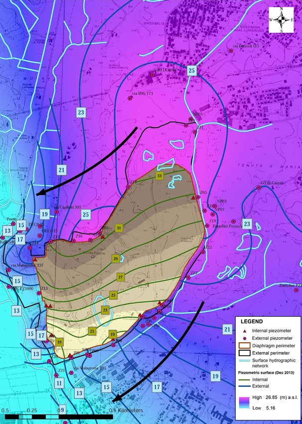
Fig. 4 - Hydraulic conditions in the Malagrotta area. Location of the plastic diaphragm and trend of isopiestic lines “internal” and “external” to the
diaphragm. Location of internal and external monitoring piezometers (modified from Piano di Caratterizzazione, Roma Capitale (2017)
was placed outside the diaphragm. For all the time steps t0-t12, motion and, in particular, flow velocity on the one hand, and
the external hydraulic heads recorded in Z7 were constantly the properties of a soil and the head loss between the points
lower than the internal ones recorded in V7. This experimental considered on the other hand. The study of a unidimensional
finding was in line with the data recorded over time by internal laminar flow of water in a soil makes it possible to measure the
(Vi) and external (Zi) piezometers along the entire perimeter of discharge per unit area, which is directly proportional to the
the diaphragm (Fig. 2). head loss between two points and inversely proportional to the
length of the flow path. In practice (see Fig. 3), the discharge Q
INVESTIGATION APPROACH per unit area can be defined by the apparent or nominal seepage
As the motion of fluids through porous media between two velocity.
generic points in a soil is governed only by the difference in Assessing the overall behaviour of the local hydrogeological
their hydraulic head, studies quantifying the water flow in a soil system was a central element of the hydraulic tests carried out
make reference to Darcy’s law. Using this law, we can identify on section V7-Z7. The boundary conditions of this system (Fig.
the fundamental links that exist between the characteristics of 3) were as follows:
Italian Journal of Engineering Geology and Environment, 2 (2021) © Sapienza Università Editrice www.ijege.uniroma1.it 55F. BRAGA & A. PRESTININZI
Fig. 5 - Hydraulic tests: trend of the piezometric head in V7 and effects recorded in Z7. t0 = 15 July 2020. The graph shows 12 time steps (t1-t12) starting
from t0, the hydraulic heads (m a.s.l.) automatically recorded by piezometer V7, and the effects induced in piezometer Z7, located outside
the cement-bentonite diaphragm. Note that the external piezometric head in Z7 is constantly below the head measured in V7 (modified from
“Relazione finale incidente probatorio”)
1. the cement-bentonite diaphragm with a thickness of 1 transmissivity of the local soils, we could change the hydraulic
m and a length L = 24.5 m; head near the measuring section. These changes were recorded
2. its internal lateral boundaries, consisting of the soil through piezometer V7. Simultaneous reading of piezometer Z7
deposits occurring between V7 and the diaphragm, (Fig. 5) demonstrated unequivocally that the interposed diaphragm
L(in); inhibited groundwater flow from the inside to the outside and vice
3. its external lateral boundaries, consisting of the soil versa. Indeed, we should not be misled by the minimum changes
deposits occurring between the diaphragm and Z7, in piezometric heads recorded externally, in piezometer Z7, in
L(out); response to changes recorded in V7. In this regard, we should point
4. its upper and lower boundaries, consisting of the out that the two heads (internal and external) were always different
topographic surface and the top of the “basal” and that the internal piezometric head was always higher than the
clays, respectively; the latter clays are known for external one. As a result of withdrawal cycles, internal groundwater
their physico-mechanical properties that qualify the level decreases/increases of the order of 1 m were accompanied by
related clayey formation as “impermeable”; they have groundwater level decreases/increases of the order of 1 cm outside
thicknesses of hundreds of metres and a grain size the diaphragm. However, these minimum changes were merely
composition consisting of over 40% by weight of silty indicative of changes in pressure and not in hydraulic flow. Indeed,
clays, with a very high clayey fraction < 2 μ (Galeotti even by using a reductio ad absurdum, it would be impossible to
et alii, 1990). assume water flow through the diaphragm, because the internal
Hydraulic surveys were carried out with reference to the water level would always remain significantly higher than the
graphs of Figs. 3, 4, and 5. external one. Moreover, as groundwater flow is controlled by
gravity (hydraulic gradient), groundwater cannot flow from lower
HYDROGEOLOGICAL ANALYSIS to higher levels. In the opposite instance, i.e. by assuming a flow
Figure 5 depicts the findings from the tests carried out on the from the inside to the outside, the external levels would receive
section shown in Fig. 3. The graph in the figure allowed us to water and thus show a tendency to increase and not to decrease,
make useful assessments of the behaviour of the above-mentioned albeit to a very small extent: without an increase in the external
hydrogeological system, in particular to test the assumption that the piezometric level, there would be no flow.
cement-bentonite diaphragm might be penetrated by fluids, driven These conditions have a rational scientific explanation if we
by the gravity-controlled hydraulic head. consider the behaviour of closed systems. Basically, closed systems
Withdrawal tests were carried out from wells placed inside can exchange energy (in this instance, pressure) but not matter (in
the cement-bentonite diaphragm. During the tests, because of the this instance, water). As displayed in the experimental graph of Fig.
56 Italian Journal of Engineering Geology and Environment, 2 (2021) © Sapienza Università Editrice www.ijege.uniroma1.itTHE CEMENT-BENTONITE DIAPHRAGM OF THE MALAGROTTA MUNICIPAL WASTE LANDFILL (ROME, ITALY): EFFICIENCY ANALYSIS
5, the head changes observed in V7 and Z7 have an instantaneous • K1 ≈ K3 = Darcy’s permeability coefficients of soils
temporal response (Δti = 0) at each time step. This is typical of occurring between V7 and the diaphragm, and between Z7
closed systems, which do not exchange matter. In geological and the diaphragm, assumed to be equal to 10-4-10-5 (m/s);
engineering, this behaviour is known as undrained behaviour, • K2 = Darcy’s permeability coefficient of the diaphragm,
in which pressure changes induce changes in a soil mass or in a with design values not higher than 10-9 (m/s).
structure, at constant volume. Both stratigraphic data and previous surveys, especially those
needed for the Malagrotta site characterisation plan, indicated that
K1 ≈ K3 >>> K2. Therefore, we assumed that k2/(k1= k3) ≈ 0. Under
these conditions, Darcy’s flow along section L (8 m) would lose all
of its head along the section of the diaphragm having the
permeability coefficient K2, i.e. along the path d = 1 m. Thus,
the hydraulic gradient would be equal to i = ΔH/d and the flow
velocity would be V= k2∙ i.
Considering a surface A, crossed by a water flow along the path
between V7 and Z7 (1 m2), the amount of fluid crossing section A
at each time step shown in Fig. 5, i.e. at t0, t1……t12, would be Q
= A ∙ k2∙ it = A ∙ V. We also resorted to a reductio ad absurdum,
i.e. imposing a velocity consistent with physical conditions in
the section considered, i.e. distance d = 1 m and fluid travel time
consistent with the data recorded in the reference piezometers of
Fig. 5: at each time step ti, the time of departure of the flow from V7
and its time of arrival at Z7 would coincide, so that the difference
between the time of departure and the time of arrival would be
equal to ∆t= (ti(in)- ti(out)) = 0.
Hence, the apparent flow velocity would be V = L/∆t = 8/(0)=
∞. If velocity takes on an infinite value, then for the relationship
V= k2∙ i to be true, it should be expressed as V = k2∙i = ∞ = k2∙∆H/d.
Recalling that the hydraulic gradient i = H/d takes on the value 0 <
i < ∞, to validate Darcy’s equation, k2 should be equal to ∞:
Tab. 2 - Proportionality ratio between the hydraulic heads in V7 and Z7,
occurring on the walls of the “internal and external” cement-
bentonite diaphragm at each time step. The statistical processing
of the data shows linear proportionality, absence of water This non-real result, obtained by imposing Darcy’s solution
exchanges, and undrained behaviour of the system investigated based on a reductio ad absurdum argument, demonstrates that the
cement-bentonite diaphragm is totally “impermeable” and thus
ANALYSIS WITH THE APPLICATION OF fully suitable for performing the function for which it was designed
DARCY’S LAW and built (Prestininzi & Romagnoli, 1991). The data shown in
Our “hydrogeological” analysis was substantiated by Darcy’s Table 2 corroborates this assumption, i.e. the hydraulic heads in V7
law, which applies to all two-phase systems (consisting of a solid and in Z7 are linked by a linear proportionality ratio, connected with
phase and of a liquid phase, regarded as not compressible). a transfer of energy (pressure), as shown in Tab 2.
Considering the geometric conditions measured along the
section V7 - diaphragm - Z7, we applied Darcy’s law with: ANALYSIS OF THE DEFORMED SHAPE OF THE
• L = 8 (m): distance between V7 and Z7; DIAPHRAGM
• D = average thickness of the diaphragm, equal to 1 (m); The findings from our hydrogeological analysis and the
• ΔH = initial piezometric head at t0, equal to (20.50-18.52) application of Darcy’s law were validated by a mechanical
= 1.98 m (14 July 2020); analysis of the elastic behaviour of the diaphragm, made up of
• it = ΔH/d hydraulic gradient, calculated for each time step a cement-bentonite mixture. The results of the application of the
ti, with i ranging from t0 to t12; note that the piezometric equations of the elastic line revealed that the undrained behaviour
head in V7 at each time step t was always higher than the of the soil-diaphragm system was in line with our analyses based
piezometric head in Z7 (Fig. 5); on experimental data from hydraulic tests and statistical tests.
Italian Journal of Engineering Geology and Environment, 2 (2021) © Sapienza Università Editrice www.ijege.uniroma1.it 57F. BRAGA & A. PRESTININZI
Based on the data already used for hydraulic investigations,
derived from the measurement of piezometric heads in V7, and
expressing all the values in kg and m, we had:
• q = head (kg/m2), evenly distributed and acting on the
cement-bentonite diaphragm wall;
• L = free length of the diaphragm (m), equal to 24.5 m,
near section V7-Z7;
• E = Young’s modulus of the cement-bentonite
diaphragm, taken to be equal to 1.4 × 10¹⁰ kg/m2
(Jefferis, 1981; Opukumo et alii, 2021; Paggi et alii,
2013);
• J = moment of inertia, equal to 0.083 m4, for a 1 m wide
diaphragm.
Through the equation of the elastic line, we defined the
displacement u(x) (m) of the diaphragm between its top position
(x = 0) and its bottom position (x = 24.5), and the corresponding
surface area Au between deformed and undeformed shape.
(1)
Tab. 3 - Statistical linearity of the proportionality ratio ΔHZ7/(C/ux (x= (2)
0), obtained through the link between the change in hydraulic
head (ΔHZ7) and the displacements of the diaphragm (arrow ux
(x = 0) and (ΔAu), induced by the internal hydraulic head (V7). a) from Eq. (1), we calculated the maximum displacement
recorded at the diaphragm top, arrow umax (x = 0), for each value of
Using Figs. 3, 6a, and 6b, we developed the equation of q measured in V7 and for the various time steps ti:
the elastic line to investigate the parameters governing the
displacements of the system considered, which were controlled (3)
by the presence of the diaphragm.
Fig. 6 - The link between the change in hydraulic head and the values of the arrow and surface area of the deformed shape is shown by the linearity
of the ΔH(Z7)/(ΔAu/umax(x=0) ratio. The figures simulate the overall displacement of the diaphragm, representing the deformation distributed
between V7 and Z7
58 Italian Journal of Engineering Geology and Environment, 2 (2021) © Sapienza Università Editrice www.ijege.uniroma1.itTHE CEMENT-BENTONITE DIAPHRAGM OF THE MALAGROTTA MUNICIPAL WASTE LANDFILL (ROME, ITALY): EFFICIENCY ANALYSIS
b) from Eq. (2), give the value of the surface area Au(max) CONCLUSIONS
related to the displacement of the diaphragm and based on the value Investigations were carried out in the area of Malagrotta
of u(max) (x = 0): (Rome, Italy), accommodating a large MSW landfill, with a
view to assessing the hydromechanical efficiency of the plastic
(4) diaphragm that had been put in place between 1986 and 1987.
The investigations showed that the diaphragm can ensure the
By using Equations (3) and (4), we computed the values umax total hydraulic discontinuity of the landfill area, as set forth in
and Aumax for all the time steps ti. Statistical processing of the Council Directive 75/442/EEC of 15 July 1975 on waste. This
data enabled us to compare all the available results: piezometric large-sized and very important structure (Figs. 1 and 2) forms an
heads in V7, piezometric heads induced in Z7, arrow umax (x = 0), environmental safety barrier around the 161 ha landfill. For safety
and surface area Aumax acting on the diaphragm. In particular, the purposes, the individual subareas of the landfill, located inside the
comparison highlighted their mutual relationships under the various diaphragm, are equipped with ordinary confinement structures, as
conditions of stress q, thereby validating the linear proportionality prescribed for MSW landfills.
of the diaphragm displacement and the origin of the piezometric Our hydrogeological and mechanical analyses demonstrated
changes ΔHZ7. Indeed, the data of Tables 2 and 3 shows the linear that the behaviour of the plastic diaphragm is in line with its
proportionality of ratios (V7/Z7) and of changes in hydraulic head design and test data. Our overall results, statistically processed,
with the data connected with the diaphragm displacement, ΔH(Z7)/ substantiated the efficiency of the diaphragm, as shown by the
[(Au)/(umax (x = 0)]. linearity of the proportionality ratios of V7/Z7 and ΔH(Z7)/(ΔAu/
The analysis of our results confirmed what we had observed umax (x = 0) (Tables 1 and 2).
during hydraulic investigations: the behaviour of the system, After more than 34 years since its construction, the cement-
subjected to hydraulic stress tests, proved to be typical of undrained bentonite plastic diaphragm retains an excellent hydromechanical
systems, which respond to stress changes with exchanges of energy efficiency, allowing it to perform its hydraulic sealing and
and induced deformations at constant volume (Figs. 3, 5, 6 a) and b)). mechanical elastic behaviour function in the future.
REFERENCES
Baconi A., Braga F., Caprili S., Gigliotti R. & Salvatore W. (2021) - Seismic demand on steel reinforcing bars in reinforced concrete frame structures.
Bulletin of Earthquake Engineering (Article in Press).
Carboni M.G. (1980) - Contributi alla stratigrafia del sottosuolo per la protezione della Campagna romana: il sondaggio Malagrotta. Boll. Soc. Geol. It. n. 99.
Calenda G. & Esu F. (1988) - Progetto esecutivo per l’adeguamento al DPR n. 915 del 10.09.1982 della discarica controllata dei rifiuti solidi sita in località
Malagrotta. Progetto approvato dalla Consulta Regionale Lazio in data 19.05.1988 (Prot. n. 31488 del 27.06.1988).
Galeotti L., Gavasci R., Prestininzi A., & Romagnoli C. (1990) - L’impatto delle attività atropiche sulle acque sotterranee dell’area di Malagrotta (Roma).
Geologia Applicata e Idrogeologia, n. 2 Carte allegate, Bari, Volume XXV.
Grisolia M., Napoleoni Q. & D’Aprile L. (2000) - Permeability laboratory test on a large specimen of cement bentonite slurry. Proc. GEOENG 2000
Melbourne (AUS).
Jefferis S.A. (1981) - Bentonite-cement slurries for hydraulic cut-offs. International Conference on Soil Mechanics and Foundation Engineering. Stockholm,
June, Vol 1: 435-440.
Opukumo A.W., Egirani D.E. & Reward K. (2021) - Stress-strain characteristics of a cement-bentonite mix for a barrier system. The implication of time and
curing. Asian Journal of Engineering and Technology, Vol. 9 (2).
Paggi M., Ferro G. & Braga F. (2013) - A multiscale approach for the seismic analysis of concrete gravity dams. Computers and Structures, 122: 230-238.
Prestininzi A. & Romagnoli C. (1991) - La vulnerabilità degli acquiferi nello smaltimento dei rifiuti. Ingegneria Sanitaria, Vol. 5: 85-94.
Prestininzi A., Brunamonte F.P., Cosentino D., D’Amico L., Gavasci R. & Romagnoli C. (1987) - Carta dei sistemi Idrogeologici del territorio della
Regione Lazio. Studio per la realizzazione del Piano Regionale di smaltimento dei rifiuti, urbani, speciali, tossici e nocivi. Assessorato ai Lavori Pubblici.
Regione Lazio.
ROMA CAPITALE (2017) - Piano di Caratterizzazione della discarica di Malagrotta. Approvazione con Determinazione Dirigenziale n. QL/233/2017.
Vespo V. S., Musso G., Guida G. & Della Vecchia G. (2021) - Studio della desaturazione di miscele cemento-bentonite indotta dall’evaporazione. X Incontro
Annuale Giovani Ingegneri Geotecnici.
Received December 2021 - Accepted January 2022
Italian Journal of Engineering Geology and Environment, 2 (2021) © Sapienza Università Editrice www.ijege.uniroma1.it 59Puoi anche leggere