SATELLITE 1I/O Replacement of IB-TRANSP1 Modulo di espansione a 1 ingresso per IB-System Manuale di installazione Expansion device 1 Input for ...
←
→
Trascrizione del contenuto della pagina
Se il tuo browser non visualizza correttamente la pagina, ti preghiamo di leggere il contenuto della pagina quaggiù
SATELLITE 1I/O
Replacement of IB-TRANSP1

  Modulo di espansione a
 1 ingresso per IB-System
 Manuale di installazione

     Expansion device
   1 Input for IB-System
   Edizione / Edition 2.1

                            20MACIE0285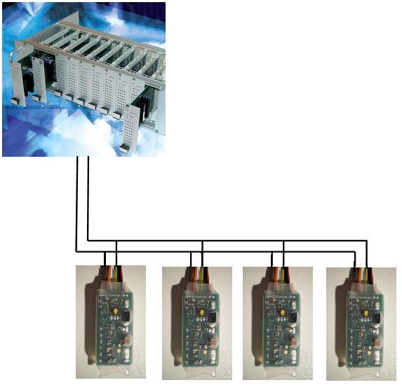
CIAS Elettronica S.r.l. Ed 2.1
INDICE
1 DESCRIZIONE ....................................................................................................................................................... 3
1.1 DESCRIZIONE ........................................................................................................................................................ 3
1.2 SCHEMA A BLOCCHI .............................................................................................................................................. 3
2 INSTALLAZIONE ................................................................................................................................................. 4
2.1 INFORMAZIONI PRELIMINARI ................................................................................................................................. 4
3 COLLEGAMENTI ................................................................................................................................................. 4
3.1 CONNESSIONI E FUNZIONALITÀ ............................................................................................................................. 4
3.2 DESCRIZIONE MORSETTI ....................................................................................................................................... 4
3.3 DESCRIZIONE FUNZIONALITÀ LED ....................................................................................................................... 5
3.4 COLLEGAMENTO ALLA ALIMENTAZIONE ............................................................................................................... 5
3.5 CONNESSIONI PER LINEA SERIALE RS-485 ........................................................................................................... 5
3.6 COLLEGAMENTO AI RIVELATORI ........................................................................................................................... 6
4 IMPOSTAZIONI .................................................................................................................................................... 6
4.1 IMPOSTAZIONE INDIRIZZO E PARAMETRI SATELLITE-1I/O .................................................................................... 6
5 APPLICAZIONI ..................................................................................................................................................... 7
5.1 APPLICAZIONI ....................................................................................................................................................... 7
6 MANUTENZIONE E ASSISTENZA .................................................................................................................... 8
6.1 TABELLA RICERCA GUASTI .................................................................................................................................... 8
7 CARATTERISTICHE ............................................................................................................................................ 8
7.1 CARATTERISTICHE TECNICHE ............................................................................................................................... 8
Manuale di Installazione Pagina 1 di 14 Satellite 1I/O CIAS Elettronica S.r.l. Ed 2.1
INDEX
1 DESCRIPTION ....................................................................................................................................................... 9
1.1 DESCRIPTION......................................................................................................................................................... 9
1.2 BLOCK SCHEMATIC ............................................................................................................................................... 9
2 INSTALLATION .................................................................................................................................................. 10
2.1 PRELIMINARY INFORMATION ............................................................................................................................... 10
3 CONNECTIONS ................................................................................................................................................... 10
3.1 CONNECTIONS AND FUNCTIONALITY ................................................................................................................... 10
3.2 TERMINAL BLOCKS.............................................................................................................................................. 10
3.3 DESCRIPTION LED FUNCTIONALITY ................................................................................................................... 11
3.4 CONNECTIONS TO POWER SUPPLY ...................................................................................................................... 11
3.5 RS-485 SERIAL LINE CONNECTIONS ................................................................................................................... 11
3.6 CONNECTIONS TO THE DETECTOR ....................................................................................................................... 12
4 SETTINGS ............................................................................................................................................................. 12
4.1 SETTING UP ADDRESS AND PARAMETERS OF SATELLITE-1I/O ........................................................................... 12
5 APPLICATIONS................................................................................................................................................... 13
5.1 APPLICATIONS ..................................................................................................................................................... 13
6 MAINTENANCE AND TROUBLE SHOOTING.............................................................................................. 14
6.1 FAULT TABLE...................................................................................................................................................... 14
7 CHARACTERISTICS .......................................................................................................................................... 14
7.1 TECHNICAL CHARACTERISTICS ........................................................................................................................... 14
Manuale di Installazione Pagina 2 di 14 Satellite 1I/O CIAS Elettronica S.r.l. Ed 2.1
1 DESCRIZIONE
1.1 Descrizione
Satellite 1I/O è il modulo di espansione da 1 INGRESSO ed 1 USCITA di CIAS
Elettronica, che consente di inviare le segnalazioni di Allarme/Tradurre gli stati fisici di una
linea bilanciata in una comunicazione digitale per mezzo del bus seriale C-ONE BUS®.
Il Satellite 1I/O è un dispositivo che permette di gestire direttamente 1 uscita in grado di
pilotare attuatori a 12V che assorbono una corrente fino a 100mA, gestire gli stati fisici di 1
rivelatore di campo specializzato per interfacciare i rivelatori di intrusione.
Attraverso la codifica del MAC-ADDRESS è possibile identificare in modo univoco,
singolarmente ogni ingresso e ogni Uscita a Relè
1.2 Schema a Blocchi
Nello schema a blocchi che segue sono rappresentati i gruppi funzionali dei dispositivi
Satellite 1I/O.
CPU
Ingresso Interfaccia
Bilanciato
RS-485
Figura 1 - Schema a blocchi Satellite1I/O con Ingresso Bilanciato
Dallo schema a blocchi (fig.1) è possibile distinguere i seguenti gruppi funzionali :
Acquisizione e gestione ingresso bilanciato, protetto da corto, taglio cavi.
Interfaccia di comunicazione per linea seriale RS-485.
Manuale di Installazione Pagina 3 di 14 Satellite 1I/O CIAS Elettronica S.r.l. Ed 2.1
2 INSTALLAZIONE
2.1 Informazioni preliminari
Satellite 1I/O è dotato di un ingresso bilanciato mediante il quale è possibile gestire diversi
criteri di segnalazione.
Con il software “Device Configuratore” è possibile, con la massima semplicità, assegnare
un identificativo per la connessione (number device), sia per l’ingresso che per l’uscita,
impostare i parametri che verranno utilizzati.
3 COLLEGAMENTI
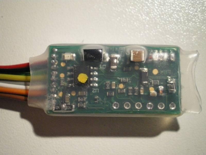
3.1 Connessioni e funzionalità
Figura 1: SATELLITE-1IO - Vista lato microprocessore
3.2 Descrizione Morsetti
CONNETTORE J1
Indicazioni per i collegamenti
Pin Colore Simbolo Funzione
1 Rosso Vin Positivo di Alimentazione 13,8V
2 Nero Gnd Negativo di Alimentazione 0V
3 Verde LH + RS485 (Linea Alta)
4 Giallo LO - RS485 (Linea Bassa)
5 Grigio Out1 Contatto di uscita optoisolato
6 Bianco Out2 Contatto di uscita optoisolato
7 Arancio A Ingresso linea bilanciata
8 Blu T Non Utilizzato
9 Marrone G Non Utilizzato
Tabella 1: SATELLITE-1IO – Connessione a J1
NB: se SATELLITE-1IO fosse l’ultima espansione della linea seriale, inserire la
terminazione di linea (resistenza da 82 ohm tra i pin 3 e 4 di J1 – fili di colore
Verde e Giallo).
Manuale di Installazione Pagina 4 di 14 Satellite 1I/O CIAS Elettronica S.r.l. Ed 2.1
3.3 Descrizione Funzionalità LED
SEGNALAZIONI LUMINOSE
Simbolo FUNZIONE
D1 Presenza alimentazione
Tabella 2: SATELLITE-1IO – Funzionalità LED
3.4 Collegamento alla alimentazione
Il modulo SATELLITE-1IO deve essere alimentato con una tensione continua di 13,8V.
La tensione di alimentazione dei dispositivi può essere prelevata direttamente dal
rivelatore a cui è connesso, oppure dall’IB-System, ponendo attenzione alla corrente
che lo stesso può fornire e all’autonomia di funzionamento richiesta per lo specifico
impianto, in assenza della tensione di rete.
Collegare l’alimentazione del modulo ai pin 1 e 2 di J1 (fili di colore Rosso e Nero –
vedi Tabella 1: SATELLITE-1IO – Connessione a J1).
3.5 Connessioni per Linea Seriale RS-485
Per connettere alla linea seriale, Satellite 1I/O collegare la linea seriale ai pin 3 e 4 di J1
(fili di colore Verde e Giallo – vedi Tabella 1: SATELLITE-1IO – Connessione a J1). La
connessione seriale deve essere effettuata mediante cavo schermato, intrecciato ed a
bassa capacità (< 70 pF/m) es. “Belden 9842”. L’architettura della rete deve essere di
tipo a “BUS”, con una lunghezza massima del bus pari a 1200 mt. Qualora fosse
necessario utilizzare una architettura stellare e la lunghezza del bus fosse superiore a
1200 mt, o il numero dei dispositivi > 32, occorre utilizzare uno o più ripetitori di linea
modello “FMCREP” o modello “BUSREP”. Per un’efficace protezione dai disturbi indotti
su tale linea occorre assicurare la continuità della connessione dello schermo, il quale
deve essere connesso a TERRA solo in un punto, per esempio in prossimità
dell’alimentatore.
Manuale di Installazione Pagina 5 di 14 Satellite 1I/O CIAS Elettronica S.r.l. Ed 2.1
3.6 Collegamento ai rivelatori
Il modulo SATELLITE-1IO può essere configurato in modalità “Bilanciato”.
Per connettere il rivelatore al modulo Satellite 1I/O è necessario che le segnalazioni di
Allarme, Manomissione e Guasto presenti sul rivelatore stesso, vengano portate
all’ingresso dell’ Satellite 1I/O mediante opportuno bilanciamento come mostrato nello
schema sotto riportato:
V
INGRESSO A RIVELATORE TRADIZIONALE 3,3V
FASCIA DI TAGLIO
470 OHM 2,9V
CONTATTO DI FASCIA DI GUASTO
470 OHM
ALLARME N.C.
2,2V
VALORI DI FASCIA DI MANOMISSIONE
BILANCIAMENTO CONTATTO DI
1000 OHM MANOMISSIONE 1,6V
PER TIPO 3 N.C. FASCIA DI ALLARME
0,9V
CONTATTO DI
1500 OHM GUASTO N.C. FASCIA DI RIPOSO
0,3V
FASCIA DI CORTO CIRCUITO
GND t
NB: L’IB-System Rack e L’IB-System IB utilizzano l’ingresso Bilanciato
4 Impostazioni
4.1 Impostazione Indirizzo e Parametri Satellite-1I/O
Per impostare l’indirizzo sul modulo dopo aver connesso l’alimentazione, è
necessario:
Collegare il SATELLITE-1IO, mediante la conversione USB-RS485 (Kit-USB), al PC
sul quale è installato il software DEVICE CONFIGURATOR
Premere il pulsante “Read Settings”, nella finestra “Device settings” verranno
visualizzati: l’indirizzo dell’ingresso, l’indirizzo dell’uscita, il MAC, il tipo di dispositivo.
I parametri del dispositivo nella lettura attualmente non sono attivi.
Per impostare l’indirizzo all’ingresso del modulo, selezionare dal menù a tenda
“Number Device” l’indirizzo desiderato.
Per impostare l’indirizzo all’uscita del modulo, selezionare dal menù a tenda
“Number Device Out (IO)” l’indirizzo desiderato
È possibile impostare il tipo di ingresso selezionando Bilanciato oppure ON/OFF,
(L’IB-System Rack e L’IB-System IB utilizzano l’ingresso Bilanciato).
Premere il pulsante “Write Settings” per inviare i parametri impostati al dispositivo.
L’operazione è avvenuta correttamente se appare il messaggio “Parametri inviati
correttamente”, diversamente ripetere l’azione.
Di seguito le credenziali per accedere via FTP e scaricare il software:
HOST USER PSW LINK
ftp.cias.it extreme extreme447 ftp://extreme:extreme447@ftp.cias.it
Manuale di Installazione Pagina 6 di 14 Satellite 1I/O CIAS Elettronica S.r.l. Ed 2.1
5 APPLICAZIONI
5.1 Applicazioni
La seguente figura mostra lo schema di connessione dell’ Satellite 1I/O alla linea seriale
dell’ IB-System.
Manuale di Installazione Pagina 7 di 14 Satellite 1I/O CIAS Elettronica S.r.l. Ed 2.1
6 MANUTENZIONE E ASSISTENZA
6.1 Tabella ricerca guasti
Difetto Possibile Causa Possibile soluzione
Controllare le connessioni
Alimentazione non presente o errata
all’alimentazione
Controllare il collegamento alla
Collegamento linea seriale errato
linea seriale RS-485
Controllare che il numero del
Numero dispositivo errato o in dispositivo impostato su
Satellite 1I/O non invia nessun
conflitto con un altro dispositivo o Satellite 1I/O sia corretto e non sia
dato sulla linea seriale
Satellite 1I/O in conflitto con nessun dispositivo
connesso alla linea seriale
Chiudere e riaprire i pin 4 e 5 di J3
Microprocessore bloccato
per resettare il microprocessore
Scheda guasta Sostituire la scheda
Controllare le connessioni sul
Connessioni ingresso errate
ingresso di Satellite 1I/O
Segnalazione dati non coerente
Controllare il bilanciamento sulla
Connessione bilanciamento errata
uscita del rivelatore
7 CARATTERISTICHE
7.1 Caratteristiche Tecniche
CARATTERISTICHE TECNICHE Min Nom Max Note
Tensione d'alimentazione (V ) 11 13,8 15,0
Corrente d'alimentazione ( mA ) - 5,8 -
Corrente contatti di uscita (mA ) 120
Tensione Contatti di Uscita (V ) 12 48
Interfaccia Linea Seriale - RS 485 -
Temperatura di lavoro (°C) - 35 - + 65
Dimensioni (mm) - 30x15 -
Peso 6g
Manuale di Installazione Pagina 8 di 14 Satellite 1I/O CIAS Elettronica S.r.l. Ed 2.1
1 DESCRIPTION
1.1 Description
The Satellite 1I/O is an expansion module from CIAS Elettronica, which can send alarm
®
signals using the C-ONE BUS serial communications, expanding the basic number of
inputs on the IB-System.
Using this expander the field inputs and outputs for the system can be up to 88.
The input of the Satellite 1I/O is designed to interface with an intruder detector.
By codification of MAC-ADDRESS it is possible to univocally and individually identify each
relay input and each relay output.
1.2 Block Schematic
The following block schematic represents the different functions of the Satellite 1I/O
device.
CPU
Balanced
Imput RS-485
Interface
picture 1 – flow diagram Satellite1I/O with Balanced Input
From the flow diagram (pic.1) the following operational groups can be distinguished:
Acquisition and management of balanced input, protected from short circuit,
cable cut.
Communication interface for serial line RS-485.
Installation Manual Page 9 of 14 Satellite 1I/O CIAS Elettronica S.r.l. Ed 2.1
2 INSTALLATION
2.1 Preliminary information
Satellite 1I/O is provided with balanced input through which it’s possible to manage
different signal parameter.
With the “Device Configurator” software it is possible, with maximum ease, appoint an ID
number for the connection (number device), both for input and for output, to set
parameters which will be in use.
3 CONNECTIONS
3.1 Connections and functionality
PICTURE 2: SATELLITE-1IO – View from microprocessor side
3.2 Terminal blocks
CONNECTOR J1
Instructions for connections
Pin Color Symbol Function
1 Red Vin Positive for power supply 13,8V
2 Nero Gnd Negative for power supply 0V
3 Verde LH + RS485 (Line High)
4 Giallo LO - RS485 (Line Low)
5 Grigio Out1 Output Contact
6 Bianco Out2 Output Contact
7 Arancio A Input for balanced line
8 Blu T Not Used
9 Marrone G Not Used
Table 3: SATELLITE-1IO – Connection to J1
NB: if the SATELLITE-1IO were the last expansion of the serial line, insert the
line termination (resistance of 82 ohm between pin 3 and 4 of J1 – Green and
Yellow wires).
Installation Manual Page 10 of 14 Satellite 1I/O CIAS Elettronica S.r.l. Ed 2.1
3.3 Description LED Functionality
LIGHT SIGNALLING
Symbol FUNCTION
D1 Power supply in activity
Table 4: SATELLITE-1IO – LED Functionality
3.4 Connections to Power Supply
The Satellite 1I/O module must be powered from DC supply of 13.8V (12V nominal).
The voltage for the device can be taken directly from the detector to which it is connected
or from the IB-System, paying attention to the current which is required and the operational
autonomy of the of the specific system, in the absence of network power.
Connect power-supply to pins 1 and 2 of J1 (Red and Black wires – see at Tabella 1:
SATELLITE-1IO – Connessione a J1).
3.5 RS-485 Serial Line Connections
To connect the serial line to the Satellite 1I/O connect the wires to terminals LH
(line high), L0 (line low) and GND of terminal block J2. The serial connection must be
made using screened, twisted cable with low capacitance (< 70 pF/m) e.g. “Belden
9842”. The bus architecture must be of the “BUS” type, with a maximum length of 1200 m.
If it is necessary to use a “star” configuration or the bus is longer tan 1200 m or the
number of devices is >32 it is necessary to use one or more bus repeaters “FMCREP”
module. For effective protection against interference along the line ensure that the screen
is interconnected throughout the length of the cable and is connected to GROUND at only
one point, usually close to the power supply.
Installation Manual Page 11 of 14 Satellite 1I/O CIAS Elettronica S.r.l. Ed 2.1
3.6 Connections to the detector
To connect the detector to the Satellite 1I/O module it is necessary that the Alarm, Tamper
and Fault contacts present on the detector are connected to the balanced input of the
transponder as shown in the following diagram:
V
INPUT XX NORMAL DETECTOR 3,3V
CUT ZONE
470 OHM 2,9V
470 OHM N.C. ALARM FAULT ZONE
CONTACT
2,2V
BALANCED TAMPER ZONE
VALUES FOR 1000 OHM N.C. TAMPER 1,6V
TYPE 3 CONTACT
ALARM ZONE
0,9V
N.C. FAULT
1500 OHM NORMAL ZONE
CONTACT
GND XX 0,3V
SHORT CIRCUIT ZONE
t
NB: by selecting “Balanced” mode “T” (Tamper) and “F” (Fault) inputs are inhibited
4 Settings
4.1 Setting up Address and Parameters of Satellite-1I/O
In order to set up address on the module after connecting power supply, you must:
Connect SATELLITE-1IO, through USB-RS485 conversion (Kit-USB), to the PC on
which the software DEVICE CONFIGURATOR has been installed
Press “Read Settings” button, on the window “Device settings” the following will be
displayed: input address, output address, MAC address, kind of device, device
parameters are not yet active for reading.
To set up the input module address, select the wanted address from the “Number
Device” drop-down menu.
To set up the output module address, select the wanted address from the “Number
Device Out (IO)” drop-down menu.
It is possible to set up the kind of input by selecting Bilanced or ON/OFF, (the IB-
System Rack and the IB-System IP use the Balanced input).
Press the button “Write Settings” to send set parameters to the device.
The procedure has been successfully performed if the message “Parameters
correctly sent” is displayed, otherwise repeat the procedure.
Please findthe code tu download the SW at ftp file as follows:
HOST USER PSW LINK
ftp.cias.it extreme extreme447 ftp://extreme:extreme447@ftp.cias.it
Installation Manual Page 12 of 14 Satellite 1I/O CIAS Elettronica S.r.l. Ed 2.1 5 APPLICATIONS 5.1 Applications The following figure shows the connection details for Satellite 1I/O to the serial line of the IB-System. Installation Manual Page 13 of 14 Satellite 1I/O
CIAS Elettronica S.r.l. Ed 2.1
6 MAINTENANCE AND TROUBLE SHOOTING
6.1 Fault Table
Fault Possible Cause Possible Solution
Power supply not present or faulty Check power supply connections
Check RS-485 serial line
Serial line connected incorrectly
connections
Check the address setting of the
Satellite 1I/O does not send data Device number wrong or in conflict Satellite 1I/O is both correct and
on the serial line with another device address not in conflict with another device
on the serial line
Close and open pins 4 and 5 of J3
Microprocessor locked
to reset the microprocessor
Faulty board Replace board
Check input connections on
Error in input connections
Satellite 1I/O
Transmitted Data incorrect
Check connections on the detector
Incorrect balanced connections
output
7 CHARACTERISTICS
7.1 Technical Characteristics
TECHNICAL CHARACTERISTICS Min Nom Max Note
Power Supply Voltage (V ) 11 13,8 15,0
Current ( mA ) - 5,8 -
Output Load Current (mA ) 120
Output Load Voltage (V ) 12 48
Serial Line Interface - RS 485 -
Working Temperature (°C) - 35 - + 65
Dimensions (mm) - 30x15 -
Weight 6g
Installation Manual Page 14 of 14 Satellite 1I/OQuesto apparecchio è contrassegnato in conformità alla Direttiva Europea 2002/96/EC, Waste Electrical and Electronic Equipment (WEEE) Assicurandosi che questo prodotto sia smaltito in modo corretto, l’utente contribuisce a prevenire le potenziali conseguenze negative per l’ambiente e la salute. Il simbolo sul prodotto o sulla documentazione d’accompagnamento indica che questo prodotto non deve essere trattato come rifiuto domestico ma deve essere consegnato presso l’idoneo punto di raccolta per il riciclaggio d’apparecchiature elettriche ed elettroniche. Disfarsene seguendo le normative locali per lo smaltimento rifiuti. Lo smaltimento abusivo è punito con le sanzioni previste dalla legislazione nazionale vigente Il prodotto può essere riconsegnato al distributore/installatore a fine vita in occasione di un nuovo acquisto. This product is marked in compliance with the European Directive 2002/96/EC, Waste Electrical and Electronic Equipment (WEEE). The correct disposal of the product will prevent potential negative consequences for the environment and the human health. The symbol on the product or into the annexed documentation indicates that this product does not have to be dealt like domestic refusal but must be delivered near the suitable point of collection for the recycling of electrical and electronic equipment. The illicit disposal will be endorsed according to local l regulations. At the end of operative life the product can be given back to the vendor/installation organization in occasion of a new purchase. Copyright CIAS Elettronica S.r.l. Stampato in Italia / Printed in Italy CIAS Elettronica S.r.l. Direzione, Ufficio Amministrativo, Ufficio Commerciale, Laboratorio di Ricerca e Sviluppo Direction, Administrative Office, Sales Office, Laboratory of Research and Development 20158 Milano, via Durando n. 38 Tel. +39 02 376716.1 Fax +39 02 39311225 Web-site: www.cias.it E-mail: info@cias.it Stabilimento / Factory 23887 Olgiate Molgora (LC), Via Don Sturzo n. 17
Puoi anche leggere