ICARO Manuale di uso e manutenzione / Manual of use and maintenance
←
→
Trascrizione del contenuto della pagina
Se il tuo browser non visualizza correttamente la pagina, ti preghiamo di leggere il contenuto della pagina quaggiù
l i nda b | we si mpl i f y c onstr u ction

ICARO
Manuale di uso e manutenzione / Manual of use and maintenance
Indice
1    Avvertenze Generali                                3
2    Descrizione dell’unità e dell’uso previsto         4
3    Tabella riepilogativa dei rischi residui           5
4    Movimentazione                                     6
5    Posizionamento ed orientamento                     7
6    Spazi tecnici-funzionali collegamento canali       8
7    Controlli preliminari                              8
8    Messa in funzione                                  9
9    Manutenzione programmata                          10
10   Tabella delle irregolarità                        11
11   Schema elettrico                                  12
12   Schede tecniche                                   13
13   Targa recuperatore                                15
14   Dichiarazione di conformità                       16

Index
1    General warnings                                   3
2    Description of the unit and intended use           4
3    Residual risks                                     5
4    Handling                                           6
5    Positioning and orientation                        7
6    Spaces technical-functional connection channels    8
7    Preliminary checks                                 8
8    Commissioning                                      9
9    Scheduled maintenance                             10
10   Troubleshooting                                   11
11   Wiring diagram                                    12
12   Technical datasheet                               13
13   Unit plate                                        15
14   Declaration of conformity                         16

2
1. Avvertenze generali
   General warnings
Il presente manuale è composto dai paragrafi indicati nell’indice: questi sono parte integrante e non possono essere separati.
E’ molto importante che l’utilizzatore finale legga il presente manuale e lo conservi in ogni sua parte.

Il presente manuale è concepito e realizzato per fornire informazioni importanti riguardo alle procedure di regolazione
ed utilizzo ordinario ma soprattutto per le fasi di vita tecnica dell’unita come la movimentazione, la messa in funzione, la
manutenzione ed infine la rottamazione. E’ di primaria importanza che:

• il manuale sia letto attentamente in ogni punto.
• il presente manuale sia conservato con cura e che sia reso disponibile all’utilizzatore e/od al responsabile della
  manutenzione.
• l’installazione e la messa in funzione siano effettuate da personale qualificato in possesso dei requisiti di
  legge (legge DM 37/08) attenendosi alle prescrizioni contenute in questo manuale.
• il costruttore declina ogni responsabilità con decadimento immediato della garanzia in caso di modifiche non
  espressamente autorizzate o manomissioni in genere che compromettano la sicurezza dell’apparecchio o non rispettino
  le indicazioni contenute in questo manuale.
• vengano osservate tutte le norme di sicurezza locali vigenti al momento dell’installazione
• il materiale di imballo utilizzato per l’unità sia tenuto lontano dalla portata dei bambini e sia correttamente
  smaltito/conferito secondo le norme locali in vigore.
• in caso di malfunzionamento dell’unità per l’eventuale riparazione ci si rivolga al costruttore che indicherà
  un centro di assistenza autorizzato: in caso contrario la garanzia dell’unità decadrà immediatamente e il
  costruttore declinerà ogni responsabilità per interventi che risultino impropri o che non si attengano alle
  disposizioni contenute nel presente manuale.

La mancata osservanza delle disposizioni contenute nel presente manuale fa decadere ogni responsabilità del costruttore
per eventuali danni subiti direttamente od indirettamente da cose o persone.

The manual present is composed from the followings paragraphs, do them of it integral part and cannot be separate.
Is very important that the final user reads the manual present and preserves him/it in every part of his.

The manual present has been conceived and realized for furnishing information important respect to the procedures of
regulation and ordinary use but above all for the phases of technical life of the united one as the handling, the in operation
mass, the maintenance and finally the scrapping. Is the primary importance that:

• the manual is attentively read in every point.
• the manual present is preserved with care and that is made available to the user and / or to the person responsible of
  the maintenance.
• the installation and the in operation mass are effected from personal qualified in possession of the requisite
  of law (DM reads 37/08) in accordance to the contained prescriptions in this manual.
• the builder expressly declines not every responsibility with immediate decadence of the guarantee in case
  of changes authorized or tampering generally that they jeopardize the safety of the instrument or doesn’t respect
  the contained indications in this manual.
• all the local safety norms are observed in force during the installation
• the material material used with the package for the unity is keep out of reach of children and is correctly
  digested/conferred according to the local norms in force
• in case of malfunction of the unity for the possible reparation turns him to the builder that will point out a centre of
  assistance authorized: in case I cross the guarantee of the unity it will immediately decay and the builder will decline
  every responsibility for interventions that result improper or that they don’t concern him to the contained dispositions
  in the manual present.

The missed observance of the contained dispositions in the manual present makes to decay every responsibility of the builder
for possible damages directly suffered or indirectly from things or people.

                                                                                                                             3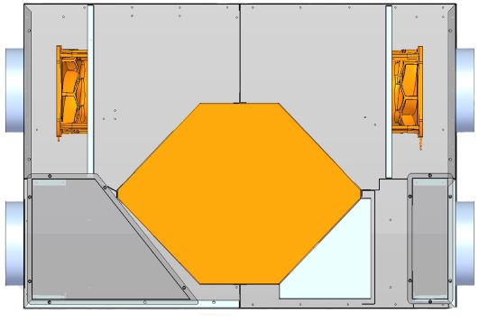
2. Descrizione dell’unità e dell’uso previsto
   Description of the unit and intended use
L’unità ICARO è un’unita per recupero di calore in una struttura in carpenteria leggera zincata per il trattamento dell’aria
primaria idonea ad un’installazione a controsoffitto (in caso contrario consultare il manuale alla sezione “Posizionamento
ed orientamento”) e per il cui corretto funzionamento è necessario provvedere all’installazione di adeguate canalizzazioni
per l’aspirazione e la mandata dell’aria. L’unità assolve alla funzione di portare le condizioni dell’aria esterna immessa in
condizioni più vicine possibili rispetto all’ambiente attuando il massimo recupero energetico sull’aria espulsa (fino al 92%).
L’unità consiste in un tipico recuperatore a flussi incrociati con ventilatori plug fan integrati dal punto di vista aeraulico. Le
sezioni di ripresa dall’ambiente e dall’esterno prevedono una filtrazione standard con filtri ondulati acrilici di grado G4.
Oltre a filtrare l’aria immessa viene così ridotto Il grado di intasamento e sporcizia dello scambiatori che condiziona in maniera
determinante le prestazioni che possono essere evitati consultando la sezione del manuale relativa alla manutenzione.

The unity ICARO, it is an united for recovery of heat in a structure in light carpentry galvanized for the treatment of the fit
primary air to an installation to suspended ceiling (in contrary case to consult the manual to the section “Positioning and
orientation”) and for whose correct operation is necessary to handle the installation of suitable canalizations for the aspiration
and eans of air supply. The unity acquits to the function to bring the conditions of the external air introduced under nearer
conditions possible in comparison to the environment effecting the maximum energetic recovery on the expelled (up to 92%)
air. The unity consists in a typical recovery to cross flows with fans plug fan integrated by the point of view aeraulic. The
sections of taken back by the environment and by the outside they foresee a standard filtering with acrylic undulated filters
of degree G4.
Besides filtering the introduced air it comes so meeting place The degree of stoppage and dirt of the exchanger that it
conditions in conclusive way the performances that can be avoided consulting the section of the manual related to the
maintenance.

    Fig. 1

    ESPULSIONE                                                                                              MANDATA
    EXTRACT                                                                                                 SUPPLY

    ARIA ESTERNA                                                                                            RIPRESA
    FRESH AIR                                                                                               EXHAUST

             Pannello rimovibile                                                           Pannello rimovibile
             accesso filtri e morsettiera elettrica                                        accesso filtri
             Removable panel                                                               Removable panel
             access filters and electrical terminal block                                   access filters

ICARO è un recuperatore statico d’aria è come tale potrebbe produrre condensa di vapore acqueo. Le unità sono
provviste di adeguati tubi di scarico in metallo ai quali devono essere applicati dei sifoni (a carico dell’installatore) che
devono essere idraulicamente collegati per consentire un corretto smaltimento della condensa secondo le norme vigenti.

The unity ICARO is a static recovery of air it is as such could produce it condenses of aqueous vapor. The unities are
provisions of suitable pipes of unloading in metal to which they must be applies of the siphons (to load of the technician)
that must hydraulically be connect for allowing a correct disposal of the it condenses according to the norms in force.

4
3. Tabella riepilogativa dei rischi residui
Residual risks
L’analisi dei rischi residui è stata effettuata come previsto dall’allegato I della Direttiva Macchine 2006/42/CEE: tutte le
avvertenze e le informazioni utili a prevenire possibili danneggiamenti a persone e/o cose a causa di rischi residui, sono
riportate in questo manuale.
L’analisi dei rischi residui delle unità a cui appartiene questo manuale è la seguente:
The analysis of the residual risks has been effected as expectation by the enclosure The of the Directive Machine 2006/42/
CEE: all the instructions and the useful information to prevent possible damages to people and/or things because of residual
risks, are brought in this manual.
The analysis of the residual risks of the unities to which this manual belongs is the following:
Rischio residuo / Residual risk
Pericolo di schiacciamento durante le operazione di La movimentazione deve essere fatta da personale
movimentazione qualificato ed esperto e devono essere rispettate le
distanze di sicurezza
Danger of crushing during the operation of handling The handling must have served as qualified and experienced
personnel and you/they must have respected the safety
distances
Pericolo di amputazione di arti e loro parti a causa delle Le bocche dei ventilatori che si affacciano all’esterno della
parti giranti in movimento macchina e che non sono protette devono essere necessa-
riamente canalizzate o dotate di cuffie antipioggia con rete
anti intrusione maglia minima 20x20
Danger of amputation of arts and them parts The mouths of the fans that lean out to the outside of the car
because of the parts endorsers in movement and that they are not protected you/they must necessarily be
canalize or endowed with bonnets rain tarp with net anti
intrusion least sweater 20x20
Pericolo di avviamenti inattesi durante la manutenzione Nel manuale ed esternamente alla macchina tramite
etichette è indicato di sezionare l’alimentazione elettrica
della macchina
Danger of unexpected start-ups during In the manual and externally to the car through labels it is
the maintenance suitable to section the power supply of the car
Rischio di caduta della macchina Nel manuale è indicato di eseguire una installazione
dell’unità idonea
Risk of fall of the machine In the manual it is suitable to perform an installation of the fit
unity
54. Movimentazione
Handling
Le operazioni qui descritte devono essere effettuate secondo le normative vigenti.
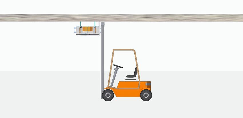
Prima di iniziare le operazioni di movimentazione assicurarsi che il peso dell’unità non superi la capacità di sollevamento
dell’attrezzatura utilizzata (consultare la scheda tecnica presente in questo manuale).
Il sollevamento della macchina può avvenire per mezzo di un sollevatore idraulico che permette il posizionamento ed in
seguito il fissaggio dell’unità al soffitto senza fatica ed in modo sicuro. Effettuare il sollevamento rispettando le distanze di
sicurezza per evitare danni indiretti a cose o persone.
The operations here described must be effect according to the normative in force.
Before beginning the operations of handling to make sure that the weight of the unity doesn’t overcome the ability of lifting
of the used equipment (to consult the present technical card).
The lifting of the car can happen through a hydraulic lifter that allows the positioning and subsequently the fixing of the unity
to the ceiling without work and in sure way. To effect the lifting respecting the safety distances to avoid indirect damages to
things or people.
Fig. 2
Ricevimento e stoccaggio
Le unità sono spedite con un imballo costituito da un pallet speciale dove le macchine (se più di una) vengono sovrapposte
l’una sopra l’altra e suddivise da un distanziale in polistirolo. E’ necessario verificare che all’arrivo dell’unità l’imballo sia integro,
che l’unità non abbia subito danneggiamenti e che sia conforme all’ordine. Nel caso di evidenti danni è necessario annotare
sul documento di trasporto il danno riportato la dicitura: RITIRO CON RISERVA PER DANNI ALL’IMBALLO. La legge n°450 del
22/08/85 prevede il risarcimento dei danni a carico dell’assicurazione nel caso di beni danneggiati per la resa franco stabilimento.
Su richiesta è possibile fornire un imballo rinforzato in legno. L’unità se non viene installata deve essere tenuta al riparo dai
principali agenti atmosferici e da condizioni climatiche gravose (max temperatura 50°C e min temperatura -10°C con 90% UR).
Reception and storage
The unities are expeditious with an I pack constituted by a special pallet where the cars (if more than one) are overlapped
the one above the other and divided by an outdistance her in polystyrene. Is necessary to verify that to the arrival of the unity
package him both entire, that the unity has not suffered damages and that is conforming to the order. In the case of evident
damage, it is necessary to annotate on the document of transport the brought damage the wording: WITHDRAWAL WITH
REVERSE FOR DAMAGE TO PACKAGE. The law 22/08/85 n°450 foresees the reimbursement of the damages to load of
the insurance in the case of damaged goods for the surrender frank establishment. On application it is possible to furnish
an I pack strengthened in wood. The unity if you is not installed must be kept to the shelter from the principal atmospheric
agents and from serious (max temperature 50°C and min temperature -10°C with 90% UR) climatic conditions.
65. Posizionamento e orientamento
Positioning and orientation
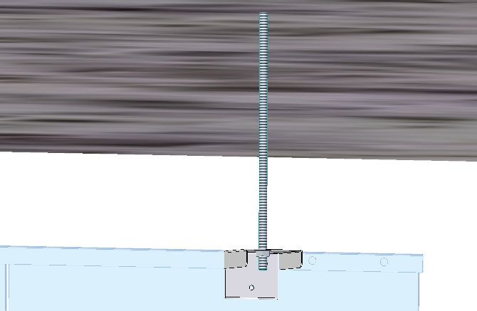
Una volta verificata l’integrità dell’imballo, rimuovere lo stesso facendo attenzione a non danneggiare l’unità e verificare
che l’unità non presenti danni visibili. La macchina deve essere posizionata in modo orizzontale per non compromettere lo
scarico condensa. La macchina può essere dotata di speciali staffe di fissaggio a soffitto (da richiedere in fase d’ordine)
che deve essere previsto di barre filettate che vengono agganciate alle staffe. In alternativa l’installatore deve prevedere una
struttura di sostegno da posizionare al di sotto del basamento inferiore della macchina avendo cura di rispettare gli spazi
necessari alla sua ispezionabilità (rimozione dei sportelli e dei filtri, vedere fig.1 a p. 4).
L’orientamento dell’unità dovrebbe essere tale da evitare che sia investita da eventuali venti predominanti che possono
influenzare il funzionamento dell’unità, in particolare la bocca del ventilatore di espulsione e la presa d’aria esterna se sono
adiacenti devono venire dotate di opportune cuffie divergenti per evitare dannose corto-circuitazioni dell’aria; se l’unità si
trova in prossimità di uffici o di locali sensibili al rumore possono essere installati a canali immediatamente dopo le bocche
dei ventilatori dei silenziatori acustici. Importante ai fini dell’installazione e di un buon funzionamento è il rispetto della messa
in bolla dell’unità ovvero la sicurezza che l’unità sia perfettamente orizzontale. Si consiglia altresì l’installazione di idonei
antivibranti da soffitto che possano lavorare in trazione tra il tetto e l’unità. L’installatore deve assicurarsi che il soffitto ed i
sistemi di aggancio allo stesso siano in gradi sopportare il peso dell’unità con un adeguato margine di sicurezza.
Once verified the integrity of the I pack, to remove the same watching out for not to damage the unity and to verify that the
unity doesn’t introduce visible damages. The machine, to avoid an ache operation, must be positions in horizontal way so
that to also avoid serious damages to the presser. The machine can be endowed with special stirrups of ceiling (to require
in phase of order) fixing that must be anticipated of bars filleted that you/they are hooked to the stirrups. In alternative the
technician must foresee a structure of support to position below the inferior plinth of the car having care to respect the
necessary spaces to her ability (removal of he counters and the filters, fig.1 p. 4).
The orientation of the unity should be such to be avoided that is invested by possible predominant winds that can influence
the operation of the unity, particularly the mouth of the fan of expulsion and the taking of external air if they are adjacent
must be come endowed with opportune divergent bonnets to avoid harmful short-circling of the air; if the unity is found in
proximity of offices or sensitive places to the noise can be immediately installed after the mouths of the fans of the acoustic
silencers. Important to the goals of the installation and a good operation it is the respect of the mass in bead of the unity or
the safety that the unity is perfectly horizontal. You also recommend the installation of fit ceiling anti vibrating that can work
in traction between the roof and the unity. The technician must make sure that the ceiling and the systems of coupling to the
same are able to bear the weight of the unity with a suitable safety border
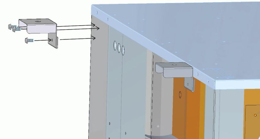
Fig. 3a Fig. 3b
Particolare fissaggio macchina a soffitto Particolare fissaggio staffa alla macchina
Particular fixing machine to ceiling Particular fixing stirrup to the machine
76. Spazi tecnici-funzionali collegamento canali
Spaces technical-functional connection channels
Gli spazi tecnici dell’unità consigliati consentono all’unità di funzionare in maniera corretta.
In particolare per una eventuale sostituzione dei ventilatori sarà necessario obbligatoriamente rimuovere la il pannello di fondo.
The technical spaces of the unity recommended allow the unity to work in correct way.
Particularly for a possible substitution of the fans it will obligatorily be necessary to remove the panel leading.
7. Controlli preliminari
Preliminary checks
Prima di dare avvio alla messa in funzione dell’unità è necessario effettuare i seguenti controlli:
1) Controllare che l’unità sia posizionata in modo corretto.
2) Dimensionare le canalizzazioni in maniera tale da assicurare un’adeguata portata d’aria per un corretto funzionamento.
3) Prevedere i silenziatori di portata dell’aria, sia sul lato di mandata sia su quello di espulsione.
4) Sigillare sempre le giunzioni tra macchina e canale in maniera da evitare perdite d’aria.
5) Controllare che la vasca di raccolta condensa dreni correttamente: a tal fine si deve verificare che agli scarichi sia
applicato un sifone e sia collegato ad una tubazione di scarico secondo le norme in vigore.
6) Controllare che le canalizzazioni siano correttamente collegate alle bocche di aspirazione e ripresa dell’unità e che non vi
siano ostruzioni al passaggio dell’aria (serrande manuali in posizione chiusa o bocchette di immissione chiuse). Assicurarsi
che, nel caso in cui le bocche di espulsione e presa di aria esterna non vengano canalizzate, siano installate delle cuffie/
plenum dotate di rete antintrusione / antivolatile.
7) Verificare che le viti di serraggio dei componenti elettrici che fissano i conduttori non siano allentate a causa delle eventuali
vibrazioni insorte nel trasporto.
Before giving start to the in operation mass of the unity it is necessary to effect the followings controls:
1) To check that the unity is positioned in correct way.
2) measure the canalizations in such way to be assured a suitable course of air for a correct operation.
3) To foresee the silencers of course of the air, both on the side of sent both on that of expulsion.
4) To always seal the junctions between car and channel in way to avoid losses of air.
5) To check that the tub of harvest condenses you correctly drain: to such end must be verified that to the discharges a
siphon is applied and is connected to a pipeline of second unloading the norms in force.
6) To check that the canalizations are correctly connected to the mouths of aspiration and resumption of the unity and that
there are no obstructions to the passage of the air (manual shutters in closed position or mouthpieces of release dams). To
make sure that, in the case in which the mouths of expulsion and taking of external air are not canalized, is installed of the
bonnets / plenum endowed with net anti intrusion / bird scarer
7) To verify that the grapevines of clamping of the electric components that stare at the conductors have not loosened
because of the possible insurgent vibrations in the transport.
Funzionamento in depressione:
H (mm) = Depressione in mmCA
S( mm) = H/2
H
Funzionamento in pressione:
T
H (mm) = 40 mm
S (mm) = pressione in mmCA
S
In alternativa la quota T può essere portata ad
un valore superiore al valore della pressione totale
in mmCA del ventilatore
NOTA BENE
Per una corretta installazione riempire il sifone di acqua e non collegarlo allo scarico in modo ermetico.
88. Messa in funzione
Commissioning
PARTE ELETTRICA
• Verificare che la tensione di rete sia di 230V.
• Assicurarsi che l’interruttore magnetotermico differenziale a monte della macchina sia opportunamente dimensionato e
che sia tarato a 0.3 A di corrente differenziale
• Verificare che arrivi ai ventilatori un segnale tra 0-10 Vdc per il corretto collegamento si rimanda alla morsettiera nello
schema elettrico
ELECTRICAL PART
• To verify that the tension of net both of 230V.
• To make sure that the interrupter differential breaker awry of the car both opportunely sized and that is set to 0.3 to
of differential tide
• To verify that reach the fans a signal among 0-10 Vdcs for the correct connection it is postponed to the terminal
block in the electric scheme
MANUTENZIONE ORDINARIA
Ad ogni avviamento stagionale dell’unità si consiglia la presenza di personale tecnico qualificato per effettuare tutti
i controlli indicati qualora la macchina non funzioni continuativamente.
! E’ molto importante assicurarsi che, prima di dare inizio a qualsiasi operazione di manutenzione, l’unità
non sia in tensione
Onde evitare il rischio di improvvisi ed inattesi avviamenti delle macchine.
Tutte le operazioni devono essere seguite conformemente alle norme vigenti in materia di sicurezza.
• Pulizia dello scambiatore: al fine di mantenere in stato ottimale lo scambio termico di degli scambiatori è necessario
rimuovere con attenzione eventuali foglie, cartacce e quant’altro possa ostruire il passaggio d’aria attraverso la
scambiatore. Questa operazione deve essere effettuata tramite una pinza a beccuccio od una spazzola, per non
danneggiare le alette e per evitare di procurarsi piccole ferite da taglio.
• Con un getto d’aria compressa soffiare dall’alto verso il basso nel senso delle alette la superficie delle alette per rimuovere
con efficacia il pulviscolo accumulato.
• Se lo scambiatore presenta delle alette piegate (solo nel caso sia in alluminio) è necessario provvedere a “pettinarle” o
con un apposito utensile oppure a raddrizzarle tramite una semplice pinza a beccuccio, prendendo ad una da una i lembi
di una aletta e provando a raddrizzarla con precisione.
• Verificare che la vasca di raccolta e scarico condensa dreni correttamente: a tal scopo verificare i sifoni.
• Verificare che all’interno dell’unità non vi siano ristagni d’acqua sospetti: in tal caso individuarne la causa ed eliminarla
(vedere note installative).
• Verificare il buon stato di conservazione della struttura e rimuovere od attenuare fenomeni di ossidazione in atto.
• Verificare che il cavo principale di alimentazione non presenti screpolature, fessurazioni o incisioni tali da compromettere
l’isolamento. Contattare il centro assistenza od una tecnico qualificato
• Verificare dopo 1 settimana dall’avviamento e poi periodicamente ogni 6 mesi od ad ogni avviamento stagionale il
serraggio di tutti i collegamenti elettrici.
• Verifica l’insorgenza di rumori e vibrazioni sospette dovute ad un’usura delle parti rotanti dei ventilatori.
REGULAR MAINTENANCE
To every seasonal starting of the unity the presence of qualified technical personnel recommends him to effect all
the suitable controls if the car doesn’t continuously work.
! Is very important to make sure that before giving beginning to any operation of maintenance THE UNITY
IS NOT IN TENSION.
Whence to avoid the risk of sudden and unexpected starting of the machine.
All the operations must accordingly have followed to the norms in force in safety subject.
• Cleaning of the exchanger: with the purpose to maintain in is optimal to exchange thermal of the exchangers it is
necessary to remove with attention possible leaves, litter and somebody else can obstruct the passage of air
through the exchanger. This operation must be effects through a pliers to lip or a brush, not to damage the fins
and to avoid to give him small hurt by cut.
• With a throw of compressed air to blow downward from the tall one in the sense of the fins the surface of the fins
to remove with effectiveness the accumulated dust.
9• If the exchanger introduces some folded up (only in the case both in aluminium) fins it is necessary to provide to
“to comb her” or with a special utensil or to straighten her through a simple pliers to lip, taking to one from one the
edges of a fin and trying to straighten it with precision.
• To verify that the tub of harvest and unloading it condenses you correctly drain: to such purpose to verify
the siphons.
• To verify that inside the unity are not you stagnate of water suspects: in such case to individualize its cause and
to eliminate (to see known installation) it.
• To verify the good state of maintenance of the structure and to remove or to attenuate phenomena of oxidation in
action.
• To verify that the principal cable of feeding doesn’t introduce cracks or such incisions to jeopardize the
isolation. To contact the centre assistance or a qualified technician
• To periodically verify after 1 week from the starting and then every 6 months or to every seasonal starting the
clamping of all the electric connections
• It verifies the onset of noises and due suspicious vibrations to a usury of the rotating parts of the fans.
9. Manutenzione programmata
Scheduled maintenance
La frequenza sopra indicata è da considerarsi puramente indicativa, in quanto diverse sono le condizioni ambientali di
applicazione dell’unità. Al fine di prevenire e migliorare nel tempo la MANUTENZIONE PROGRAMMATA adeguandola così
alle reali necessità ambientali, è buona norma che ad ogni controllo periodico venga comunque effettuato un controllo visivo
delle parte sensibili e sottoposte ad usura.
The frequency above suitable it is him to consider purely indicative, in how much different they are the environmental
conditions of application of the unity. With the purpose to prevent and to improve in the time the PROGRAMMED
MAINTENANCE adjusting her/it so to the real environmental necessities, it is good norm that to every periodic control a
visual control of the sensitive parts is effected however and submitted to usury.
Ogni 2000h Ogni Ogni
Operazione da effettuare Ogni mese di lavoro 6 mesi Ogni anno 2 anni
Operation to be effected Every month Every 2000h Every 6 Every year Every 2
of job months years
Cambio filtri
• •
Change filters
Controllo Stato intasamento Filtri
•
Check state stoppage filter
Controllo serraggio morsetti
•
Check clamping clamps
Pulizia Ventilatori Cleaning fans •
Pulizia Recuperatore
•
Cleaning recovery
Pulizia vasche interne
•
Cleaning inside tubs
MESSA FUORI SERVIZIO E ROTTAMAZIONE DELL’UNITA’
Qualsiasi operazione di messa fuori servizio dell’unità deve fare riferimento a questo manuale per quanto riguarda le
operazioni di accesso all’unita, scollegamento degli allacciamenti elettrici, aeraulici.
Ogni componente facente parte dell’unità deve considerarsi un rifiuto speciale e non può essere gettato nelle immondizie
comuni ma va smaltito secondo le normative locali e vigenti al momento della rottamazione.
PUT OFF DUTY AND SCRAPPING OF THE UNIT
Any operation of put of the unity off duty must make reference to this manual as it regards the operations of access to the
united one, disconnection of the electric lacings, aeraulic.
Every component doing part of the unity must consider him a special refusal and cannot be thrown in the common garbage
but must be digested according to the normative local and in force during the scrapping.
1010. Tabella delle irregolarità
Troubleshooting
Lo scopo della presente tabella è indirizzare il personale qualificato ad una veloce diagnosi e risoluzione delle eventuali
anomalie riscontrate sulle unità.
The purpose of the present chart is to address the qualified personnel to a fast diagnosis and resolution of the possible
anomalies found on the units.
ANOMALIA CAUSA RIMEDIO
ANOMALY CAUSE REMEDY
Assorbimenti anomali Ostruzioni nei canali, eccessive o Rimuovere le ostruzioni, ridurre le
dei ventilatori basse perdite di carico nei canali perdite di carico, creare delle perdite
di carico aggiuntive
Anomalous absorptions Obstructions in the channels, To remove the obstructions, to
of the fans excessive or low losses of load in reduce the losses of load to
the channels create some additional losses
of load
Portata d’aria insufficiente Ventilatore al di fuori dei limiti di Verificare i dati di targa del motore e le
o mancante funzionamento. prevalenze nominali
Course of insufficient Fan out of the limits of operation To verify the data of plate of the motor
or lacking air and the nominal prevalence
Filtri aria intasati. Pulire o sostituire i filtri
Air filter clogged Clean or to replace the filters
1112
PE N
2
4
8
6
12
AO1 IN1 IN2 IN3 IN4 IN5 IN6 +12VdcGND
GND DATA +12Vdc + - GND AO2 GNDIN10IN9 IN8 IN7 GND OC1
3
7
9
1 2 3 MODBUS
INTRABUS
EVCO PE 1 2 3 4 5 6 7 8 9 10 11 12 13 14 15 16 17
11. Schemi elettrici
Wiring diagrams
EVD934BM9VMC
with remote easy panel - EV3K11X0CT
GND
0-10Vdc
EVD934BM9MF VMC Tachimetrico Ventilatore Espulsione / Return Tach. Frequency
Tachimetrico Ventilatore Mandata / Supply Tach. Frequency
Uscita Segnalazione Allarme / Alarm Relay - 230Vac
NO1 NO2 CO1/2 NO3 CO3/4 CO3/4 NO4 NC4 V~ V~
m Uscita Apertura Serranda By-pass / By-pass Damper Control - 230Vac
10 AX L
M
con display semplificato remotizzabile - EV3K11X0CT
EVCO
EV3K11X0CT 1 2 3 4
+12VdcGNDDATA GND
18 19 20 21 22 23 24 25 26 27 28 29 30 31 32
Sonda NTC
Aria Esterna
External Air
NTC Probe
EVCO
EV3K11X0CT 1 2 3 4
+12VdcGNDDATA GND
m Filtro Sporco
30 AX Clogged Filter
M L Servomotore Serranda
Sonda NTC Predisposizione
230Vac - 50Hz 12Vac - 50Hz Aria Ambiente On/Off Remoto Damper Actuator Alimentazione 230Vac
N Ambient Air Predisposition for 230Vac Power Supply
NTC Probe Remote On/Off
25H-50H-80HPE N
2
4
8
6
12
AO1 IN1 IN2 IN3 IN4 IN5 IN6 +12VdcGND
GND DATA +12Vdc + - GND AO2 GNDIN10IN9 IN8 IN7 GND OC1
3
7
9
1 2 3 MODBUS
INTRABUS
EVCO PE 1 2 3 4 5 6 7 8 9 10 11 12 13 14 15 16 17
EVD934BM9 VMC
GND
with remote advanced panel - EVJD900N2VW
0-10Vdc
EVD934BM9MF VMC Tachimetrico Ventilatore Espulsione / Return Tach. Frequency
Tachimetrico Ventilatore Mandata / Supply Tach. Frequency
con display evoluto remotizzabile - EVJD900N2VW
m
Uscita Segnalazione Allarme / Alarm Relay - 230Vac
NO1 NO2 CO1/2 NO3 CO3/4 CO3/4 NO4 NC4 V~ V~
Uscita Apertura Serranda By-pass / By-pass Damper Control - 230Vac
10 AX
M
L
EVCO EVCO
EVJD900N2VW L EVJD900N2VW
230Vac - 50Hz
GND 6 N GND 6
18 19 20 21 22 23 24 25 26 27 28 29 30 31 32
Sonda NTC
IN4 5 IN4 5 Aria Esterna
External Air
12V 4 12V 4 NTC Probe
12Vac - 50Hz
12V 3 12V 3
IB 2 2 DATA IB 2
m Filtro Sporco
GND 1 1 GND 30 AX GND 1 Clogged Filter
M
Sonda NTC Predisposizione Servomotore Serranda Alimentazione 230Vac
Aria Ambiente On/Off Remoto Damper Actuator 230Vac Power Supply
25H-50H-80H
Ambient Air Predisposition for
NTC Probe Remote On/Off
1314
PE N
2
4
8
6
10
12
AO1 IN1 IN2 IN3 IN4 IN5 IN6 +12VdcGND
GND DATA +12Vdc + - GND AO2 GNDIN10IN9 IN8 IN7 GND OC1
3
9
1 2 3 MODBUS
INTRABUS
EVCO PE 1 2 3 4 5 6 7 8 9 10 11 12 13 14 15 16 17
11. Schemi elettrici
EVD934BM9 VMC
Wiring diagrams
with remote easy panel - EV3K11X0CT
GND
0-10Vdc
EVD934BM9MF VMC Contatto Digitale Guasto Ventilatore Espulsione / Return Fan Digital Contact Fault Reporting
Contatto Digitale Guasto Ventilatore Mandata / Supply Fan Digital Contact Fault Reporting
Uscita Segnalazione Allarme / Alarm Relay - 230Vac
NO1 NO2CO1/2 NO3CO3/4CO3/4 NO4 NC4 V~ V~
m Uscita Apertura Serranda By-pass / By-pass Damper Control - 230Vac
10 AX L
M
con display semplificato remotizzabile - EV3K11X0CT
EVCO
EV3K11X0CT 1 2 3 4
+12VdcGNDDATA GND
18 19 20 21 22 23 24 25 26 27 28 29 30 31 32
Sonda NTC
Aria Esterna
External Air
NTC Probe
EVCO
EV3K11X0CT 1 2 3 4
+12VdcGNDDATA GND
m Filtro Sporco
30 AX Clogged Filter
M L Servomotore Serranda
Sonda NTC Predisposizione
230Vac - 50Hz 12Vac - 50Hz Aria Ambiente On/Off Remoto Damper Actuator Alimentazione 230Vac
N Ambient Air Predisposition for 230Vac Power Supply
NTC Probe Remote On/Off
120H - 150HPE N
2
4
8
6
10
12
AO1 IN1 IN2 IN3 IN4 IN5 IN6 +12VdcGND
GND DATA +12Vdc + - GND AO2 GNDIN10IN9 IN8 IN7 GND OC1
3
7
9
1 2 3 MODBUS
INTRABUS
EVCO PE 1 2 3 4 5 6 7 8 9 10 11 12 13 14 15 16 17
EVD934BM9 VMC
GND
with remote advanced panel - EVJD900N2VW
0-10Vdc
EVD934BM9MF VMC Contatto Digitale Guasto Ventilatore Espulsione / Return Fan Digital Contact Fault Reporting
Contatto Digitale Guasto Ventilatore Mandata / Supply Fan Digital Contact Fault Reporting
con display evoluto remotizzabile - EVJD900N2VW
m
Uscita Segnalazione Allarme / Alarm Relay - 230Vac
NO1 NO2 CO1/2 NO3 CO3/4 CO3/4 NO4 NC4 V~ V~
Uscita Apertura Serranda By-pass / By-pass Damper Control - 230Vac
10 AX
M
L
EVCO EVCO
EVJD900N2VW L EVJD900N2VW
230Vac - 50Hz
GND 6 N GND 6
18 19 20 21 22 23 24 25 26 27 28 29 30 31 32
Sonda NTC
IN4 5 IN4 5 Aria Esterna
External Air
12V 4 12V 4 NTC Probe
12Vac - 50Hz
12V 3 12V 3
IB 2 2 DATA IB 2
m Filtro Sporco
GND 1 1 GND 30 AX GND 1 Clogged Filter
M
Sonda NTC Predisposizione Servomotore Serranda Alimentazione 230Vac
Damper Actuator 230Vac Power Supply
120H - 150H
Aria Ambiente On/Off Remoto
Ambient Air Predisposition for
NTC Probe Remote On/Off
1512. Schede tecniche
Technical datasheet
L Dimensioni / Dimensions
H
Ø
P
Ø
Ø
Ø
Modello L P H Ø Dimensione filtri
Model mm mm mm mm Filter dimensions
ICARO 025H 925 726 250 200 300x240x98
ICARO 050H 925 726 335 200 300x320x98
ICARO 080H 1355 906 335 250 350x320x98
ICARO 120H 1850 1100 405 315 400x390x98
ICARO 150H 1850 1100 405 315 400x390x98
Dati tecnici / Technical data
Portata/Prevalenza Alimentazione Corrente Potenza Livello di Peso
Airflow/Pressure Supply voltage max ass. max ass pressione sonora Weight
Modello (ErP 2018) Current Power Sound power
Model absorbed max absorbed max level
m3/h - Pa V/ph/Hz A W Lpa dB(A) Kg
ICARO 025H 250 m3/h 100 Pa 230/1/50 1,0 140 46 38
ICARO 050H 500 m3/h 100 Pa 230/1/50 2,2 340 50 45
ICARO 080H 800 m3/h 150 Pa 230/1/50 2,4 400 51 76
ICARO 120H 1200 m3/h 150 Pa 230/1/50 7,4 1700 53 115
ICARO 150H 1500 m3/h 150 Pa 230/1/50 7,4 1700 54 115
16Fissaggio / Suspension
L’unità è provvista di staffe alle quali è possibile agganciarsi con barre filettate per agevolare il fissaggio
al pavimento/soffitto.
The unit is equipped with lifting rods,where hooking is possible through threaded bars or chains in order
to facilitate floor/celing fastening.
a
Modello a b
Model mm mm
ICARO 025H 741 790
b
ICARO 050H 741 790
ICARO 080H 1169 972
a1 a2
Modello a1 a2 b
Model mm mm mm
ICARO 120H 894 894 1154
ICARO 150H 894 894 1154
b
1713. Targa recuperatore
Unit plate
>ĂƌŐŽƵŐƵƐƚŽ͕ϳͲϮϬϭϮϮDŝůĂŶŽ;D/Ϳ
;;;;;; ŶŶŽĚŝĨĂďďƌŝĐĂnjŝŽŶĞ
ϮϬϭϴ
DŽĚĞůůŽ dLJƉ
DŽĚĞůůŽͬdLJƉĞ
/ZKϮϱ, DŽĚĞůğ
DĂƚƌŝĐŽůĂ ^ĞƌŝŶŶƵŵŵĞƌ
^ĞƌŝĂůEƵŵďĞƌ yyyyyy DĂƚƌŝĐƵůĞ
dĞŶƐŝŽŶĞEŽŵŝŶĂůĞ EĞŶŶƐƉĂŶŶƵŶŐ
sŽůƚĂŐĞ^ƵƉƉůLJ
ϮϯϬͬϭͬϱϬнEнW
dĞŶƐŝŽŶEŽŵŝŶĂůĞ
WŽƚĞŶnjĂƐƐŽƌďŝƚĂ >ĞŝƐƚƵŶŐƐĂƵĨŶĂŚŵĞ
WŽǁĞƌŽŶƐƵŵƉƚŝŽŶ
ϭϳϬt WƵŝƐƐĂŶĐĞ
ůĞĐƚƌŝƋƵĞ
ŽƌƌĞŶƚĞEŽŵŝŶĂůĞ EĞŶŶƐƚƌŽŵ
ZƵŶŶŝŶŐƵƌƌĞŶƚ
ϭ͕ϲ /ŶƚĞƐŝƚğ
WŽƌƚĂƚĂĂƌŝĂ >ƵĨƚƐƚƌŽŵ
ŝƌĨůŽǁ
ϮϱϬŵϯͬŚ &ůƵdžĚΖĂŝƌ
WƌĞǀĂůĞŶnjĂƵƚŝůĞ EƵƚnjĨƂƌĚĞƌŚƂŚĞ
ǀŝĂďůĞƉƌĞƐƐƵƌĞ
ϭϬϬWĂ WƌĠǀĂůĞŶĐĞƵƚŝůĞ
WĞƐŽ 'ĞǁŝĐŚƚ
tĞŝŐŚƚ
ϯϴŬŐ WŽŝĚƐ
1814. Dichiarazione di conformità
Declaration of conformity
Dichiarazione di Conformità - Declaration of Conformity
Si dichiara, sotto la nostra responsabilità, che l’insieme sotto indicato è conforme alle seguenti norme armonizzate qui di seguito
elencate soddisfacendo i requisiti essenziali delle direttive sotto riportate
Modello - Model ICARO 025 H 050H 080H
Anno di costruzione
2018
Year of manifacture
Norme armonizzate
EN 378-1 a -4 Impianti di refrigerazione e pompe di calore - Refrigerating systems and heat pumps
EN 60204-1:2006 Sicurezza del macchinario-Equipaggiamento elettrico - Parte 1: Regole generali - Safety of machinery.
Electrical equipment of machines. General requirements
EN 60335-2-40 Norma di sicurezza riguardante le pompe di calore elettriche, i condizionatori d’aria
e i deumidificatori - Household and similar electrical appliances - Safety - Part 2-40: Particul requirements
for electrical heat pumps, air-conditioners and dehumidifiers
EN 61000-6-1:2007
Compatibilità elettromagnetica – Ambiente residenziale Immunità ed emissione Electromagnetic compati-
EN 61000-6-3:2007
bility (EMC). Generic standards. Immunity for residential, commercia and light-industrial environments
EN 61000-6-2 :2005
Compatibilità elettromagnetica – Ambiente industriale Immunità ed emissione
EN 61000-6-4 :2007
Electromagnetic compatibility (EMC). Generic standards. Immunity for industrial environment
EN ISO 12100-1-2:2003 Sicurezza del macchinario-Concetti fondamentali, principi generali di progettazione. Specifich e principi
tecnici Safety of machinery -- Basic concepts, general principles for design -- Part 2
Technical principles
EN ISO 13857:2008 Sicurezza del macchinario-Distanze di sicurezza per impedire il raggiungimento di zone pericolose con gli
arti superiori
EN 349:1993 + A1:2008 Sicurezza del macchinario-Spazi minimi per evitare lo schiacciamento di parti del corpo uma
Safety of machinery -- Safety distances to prevent hazard zones being reached by upper and lower limbs
ErP 2009/125/CE Istituzione di un quadro per l’elaborazione di specifiche per la progettazione ecocompatibile d prodotti
connessi all’energia. Establishing a framework for the setting of ecodesign requirements for energy-re-
lated produc
Direttive CEE
2014/30/UE Compatibilità elettromagnetica Electromagnetic Compatibility Directive
2014/35/UE Bassa tensione Low Voltage Directive
Data Firma del legale rappresentante
Michele Paccagnella
.....................................
19At Lindab, good thinking is a philosophy that gui-
des us in everything we do. We have made it our
mission to create a healthy indoor climate – and
to simplify the construction of sustainable buil-
dings. We do that by designing innovative pro-
ducts and solutions that are easy to use, as well
as offering efficient availability and logistics. We
are also working on ways to reduce our impact on
our environment and climate. We do that by de-
veloping methods to produce our solutions using
a minimum of energy and natural resources, and
by reducing negative effects on the environment.
We use steel in our products. It’s one of few materi-
als that can be recycled an infinite number of times
without losing any of its properties. That means
less carbon emissions in nature and less energy
wasted.
We simplify construction
www.lindab.comPuoi anche leggere