SISTEMI PER IMPIANTI DI TERRA - PARAFULMINI - EQUIPOTENZIALI LPS ESTERNI EARTHING SYSTEMS - LIGHTNING PROTECTION - EQUIPOTENTIAL EXTERNAL LPS
←
→
Trascrizione del contenuto della pagina
Se il tuo browser non visualizza correttamente la pagina, ti preghiamo di leggere il contenuto della pagina quaggiù

Via Ferrero, 10 - 10098 Rivoli (TO) Italy
      Telefono +39 011.95.90.111
 Fax Commerciale: +39 011.95.90.200
Fax Amministrativo: +39 011.95.90.230
           info.sati@sati.it                SISTEMI PER IMPIANTI DI TERRA - PARAFULMINI - EQUIPOTENZIALI
              www.sati.it                   LPS ESTERNI
                                            EARTHING SYSTEMS - LIGHTNING PROTECTION - EQUIPOTENTIAL
                                            EXTERNAL LPS

                                                                               QUADERNO TECNICO
                                                                                   TECHNICAL LOG

                                                                   WWW.SATI.IT
Sati Italia S.p.A.                                                                              Capogruppo
                                                                                                       Via Ferrero, 10 - 10098

      storia in continua
                                                                                                       Rivoli (TO) Italy
                                                                                                       Tel.: +39.011.95.90.111

         evoluzione
                                                                                                       Fax Comm.: +39.011.95.90.200
                                                                                                       Fax Amm.: +39.011.95.90.230
                                                                                                       www.sati.it
Sati Italia S.p.A è entrata a far parte delle attività commerciali
del Gruppo Carpaneto Sati oltre 25 anni fa’.
Sati Italia propone al mercato un’offerta di prodotti e
soluzioni legate al settore dell’impiantistica elettrica
industriale e il suo core business si identifica nell’ampia
gamma di sistemi di canalizzazione metallica portacavi
suddivisa in: sistemi di canalizzazione nella versione chiusa
e forata “Linea S5”, sistema di passerella a filo “Linea S2”,
sistema di passerelle a traversini “Linea S3”.
La produzione di queste principali linee di prodotto e le
lavorazioni di Zincatura a Caldo dopo lavorazione e
Verniciatura a Polveri sono processi realizzati all’interno
dello stabilimento Procan S.r.l di Latina, sito produttivo di
proprietà Sati Italia S.p.A.
Il Catalogo canalizzazioni, inoltre, si completa con altri
sistemi a supporto e di sospensione del canale (mensole,
profili, giunti, ecc..) ed infine con un sistema modulare
molto pratico, veloce ed economico, compatibile con gli
accessori dei sistemi di sospensione, noto al mercato come
“Linea Sati Speed”.
Sati Italia S.p.A. da marzo 2017 ha ampliato ulteriormente la                 history in continuous
propria gamma di prodotti, rendendo ancora più completa
la propria offerta commerciale. Sati in Italia che affianca al
proprio core business del canale metallico, una offerta
                                                                                    evolution
complementare e alternativa per un impianto elettrico
industriale che è quella del condotto sbarre.                        Sati Italia S.p.A. was acquired in 1991 and recently celebrated
                                                                     its first 25 years as part of the Carpaneto Sati Group.
Sati Italia propone pertanto la propria gamma di condotti            Sati Italia offers a range of products and solutions for industrial
sbarre, attualmente riassunti in un catalogo appositamente           electrical systems and its core business consists of a wide range
realizzato per presentare: la Linea SATIIDEA (Condotto               of cable trunking systems, which includes: “Line S5” closed and
Sbarre Luce) la Linea SATISTART (Condotto Sbarre Potenza             perforated trunking systems, “Line S2” mesh wire cable tray
fino a 250A), la Linea SATIGO (Condotto Sbarre Potenza fino          systems and “Line S3” cable ladder systems.
a 1000A.) e la linea SATIWIN (Condotto Sbarre Compatto               The production of these main product lines and the Hot-dip
fino a 5000A).                                                       Galvanizing and Powder Coating processes are carried out by
L’offerta Sati Italia, però, include, altre linee di prodotto e      the Procan S.r.l plant in Latina, a production site owned by Sati
soluzioni, che sono state integrate nel corso degli anni, a          Italia S.p.A. Furthermore, the cable trunking Catalogue includes
                                                                     other support systems such as suspension systems (brackets,
partire da linee di prodotto più storiche, quali: Sistemi per        profiles, joints, etc.) and, finally, a very practical, fast and cheap
Impianti di Terra, Parafulmine ed Equipotenziali, LPS -              modular system, which is compatible with the suspension
Esterni e Sistemi di Barriere Tagliafiamma per la Protezione         system accessories and is known as the “Sati Speed Line”.
Passiva, arrivando alle linee di prodotto introdotte più             Following the industrial agreement signed with Naxso S.r.l. in
recentemente, come: la linea dedicata agli articoli per              March 2017, Sati Italia S.p.A., has further expanded its range of
fissaggio destinati al settore elettrico “Linea Sati Nobex”.         products, thus further enhancing its commercial offering.
Ciascuna linea di prodotto Sati Italia ha un proprio catalogo        Sati Italia S.p.A. since March 2017, has further expanded its
di riferimento, sia in versione tipografica che in versione          product range. Sati brand in Italy, which combines its core
digitale, disponibile nell’area documentazione, nel sito             business of the metal channel with a complementary and
www.sati.it. costantemente aggiornato.                               alternative offer for an industrial electrical system that is the
                                                                     busbar conduit.
Sati Italia garantisce la propria assistenza tecnica e servizio
logistico grazie alle 4 sedi operative dislocate sul territorio      Sati Italia therefore offers its own range of busbar conduits,
                                                                     currently summarised in a catalogue specifically designed to
nazionale a Torino, Pavia, Padova e Latina. Dal 2007 è               present: the SATIIDEA Line (Busbar Light Conduit), the SATISTART
presente anche in Nord Africa con una propria filiale a              Line (Busbar Power Conduit up to 250A), the SATIGO Line
Tunisi: la Sati Tunisia S.a.r.l.                                     (Busbar Power Conduit up to 1000A.) and the SATIWIN Line
                                                                     (Compact Busbar Power Conduit up to 5000A).
                                                                     However, Sati Italia also offers other product lines and
                                                                     solutions, which have been incorporated over the years. These
                                                                     range from more traditional product lines, such as Earthing
                                                                     systems, Lightning Protection and Equipotential Bonding
                                                                     Systems, External LPS and Passive Fire Protection Systems, to
                                                                     the more recently introduced new product lines, such as the line
                                                                     dedicated to fastening devices for the electrical sector, the “Sati
                                                                     Nobex Line”.
                                                                     Each Sati Italia product line has its own recently-updated
                                                                     catalogue, both printed and digital, which is available in the
                                                                     documentation area of the website www.sati.it.
                                                                     Sati boasts 4 operational headquarters in Italy, located in
                                                                     Siziano (PV), Turin, Padua and Latina, covering a total area of
                                                                     20,000 square metres.
                                                                     The organisation employees around 60 in-house staff and
                                                                     collaborates with 15 sales agencies throughout the country.
                                                                     Sati has also had a base in North Africa since 2007, with its own
                                                                     subsidiary, Sati Tunisia S.a.r.l. located in Tunis.
                                    www.sati.it
SEDI E FILIALI DELLA SATI ITALIA
HEADQUARTERS AND BRANCHES OF SATI ITALIA

                                                 SIZIANO - Centro logistico nord-ovest Italia e filiale commerciale
                                                 Via Monviso, 5 - 27010 SIZIANO (PV) Italy
                                                 Tel. +39.0382.678.311
                                                 Fax Commerciale +39.0382.678.312
                                                 Fax Amministrazione +39.011.95.90.230
                                                 www.sati.it

    PADOVA - Centro logistico nord-est Italia e filiale commerciale
    Viale dell’Industria, 84 - 35129 PADOVA - Italy
    Tel. +39.049.80.89.120
    Fax +39.049.80.89.165
    www.sati.it

                                                 LATINA - Centro logistico centro-sud Italia
                                                 S.S. 148 Pontina Km 81,400 n. 239
                                                 04100 BORGO GRAPPA (LT) Italy
                                                 Tel. +39.011.95.90.111
                                                 Fax +39.011.95.90.200
                                                 www.sati.it

               LATINA - Stabilimento di Produzione
               S.S. 148 Pontina Km 81,400
               04100 BORGO GRAPPA (LT) Italy
               www.procan.it

       Per trovare l’Agenzia di zona consultare il sito internet
             www.sati.it nella sezione “Rete Vendita”.

2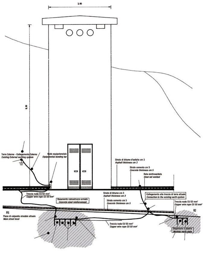
LE ALTRE ATTIVITÀ DEL GRUPPO CARPANETO SATI
OTHER ACTIVITIES OF THE CARPANETO SATI GROUP

                    www.gruppocarpanetosati.it

                                 Sede operativa e centro logistico
                                 Siziano (PV) - Italy
                                 www.nobex.it

                        Sede legale e operativa
                        Rivoli (TO) - Italy
                        www.satishielding.it

                                 Sede operativa e di produzione
                                 Tunisi – Tunisia
                                 www.satitunisia.com

                        Sede legale e operativa WIT S.A.
                        Nice - France
                        www.wit.fr

                                                                     3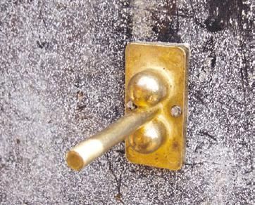
CERTIFICAZIONI DEL SISTEMA QUALITÀ AZIENDALE
COMPANY QUALITY SYSTEM CERTIFICATION

La Qualità come fattore di miglioramento strategico           Quality as a strategic improvement factor of
della Sati Italia S.p.A..                                     Sati Italia S.p.A.
La Gestione della Qualità è, da sempre, un impegno            Quality Management has always been a steadfast
costante della politica aziendale della Sati Italia S.p.A..   commitment for the company policy of Sati Italia
                                                              S.p.A..
Impegno che, certificato già dal 1997, si è ulteriormente
ampliato con la certificazione ottenuta a novembre            Initially certified in 1997, this pledge has grown with
2017 in conformità alla norma UNI EN ISO 9001:2015            the UNI EN ISO 9001:2015 certification obtained in
che mette in risalto:                                         November, which highlights:
• la “soddisfazione del cliente” rivolta ai prodotti e        • “customer satisfaction” aimed at Sati Italia S.p.A.
  servizi della Sati Italia S.p.A.                              products and services
• la rispondenza dei nostri prodotti alle Direttive CEE       • the compliance of our products with CEE Directives
  per la marcatura                                              for marking
• la qualità costante dei prodotti, nel rispetto delle        • the lasting quality of our products, in accordance
  norme e specifiche tecniche applicabili.                      with applicable technical specifications and
• Sati Italia S.p.A. ha ottenuto il rinnovo della               standards.
  certificazione del Sistema di Qualità Aziendale per il      • Sati Italia S.p.A. obtained the renewal of the
  triennio 2017 - 2020.                                         Company Quality System certification for the period
                                                                2017 - 2020.
Questo risultato è stato possibile grazie alle
disposizioni della direzione aziendale ed all’impegno         This result was made possible thanks to measures
costante e responsabile delle risorse umane della             taken by the company management and the constant
Sati Italia S.p.A., operando nell’ambito di una strategia     and responsible commitment of the human resources
fatta di obiettivi, strutture organizzative e mezzi           department at Sati Italia S.p.A., working hard towards
tecnici d’avanguardia.                                        a strategy made of goals, organisation structures and
                                                              cutting edge technical means.

4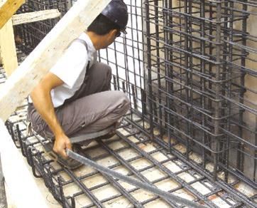
SISTEMI PER IMPIANTI DI TERRA, PARAFULMINE
ED EQUIPOTENZIALI - LPS ESTERNI
EARTHING SYSTEMS, LIGHTNING PROTECTION AND
EQUIPOTENTIAL BONDING SYSTEMS - EXTERNAL LPS

• Sistemi per impianti di terra - note tecniche................................... pag.                             6
  Earthing systems - technical notes
• Sistemi per impianti parafulmini - note tecniche........................... pag.                                 10
  Lightning systems - technical notes
• Sistemi per collegamenti equipotenziali - note tecniche............... pag.                                      16
  Equipotential bonding systems - technical notes
• Sistemi TT per edifici ad uso abitativo e terziario........................... pag.                              18
  TT systems for homes and commercial buildings
• Sistemi TN per industrie, centri commerciali, alberghi.................. pag.                                    20
  TN systems for industrial plants, shopping centres and hotels
• Sistemi IT............................................................................................... pag.   20
  IT Systems
• Torri Piezometriche............................................................................. pag.            22
  Watering towers
• Cabine con scaricatori MT................................................................... pag.                24
  Cabins HV/LV equipped with Surge Protective Device
• Cabine su terreni difficili.................................................................... pag.             26
  Cabins HV/LV on difficult terrain
• Capannoni Prefabbricati ed Equipotenzialità.................................. pag.                               28
  Prefabricated Warehouses and Equipotentiality
• Terre di fondazione - note tecniche................................................... pag.                      30
  Foundation earth electrode - Technical notes
• Collegamenti impropri ai ferri di armatura del calcestruzzo......... pag.                                        33
  Improper connections to reinforcements of reinforced concrete

Prodotti consultabili Catalogo Generale 2017 o sul sito www.sati.it
Products available on the General Catalogue 2017 or on website www.sati.it
SISTEMI PER IMPIANTI DI TERRA
EARTHING SYSTEMS
ESEMPIO DI IMPIANTO DI TERRA / EXAMPLE OF AN EARTHING SYSTEM
SCELTA DEI COMPONENTI CHOICE OF COMPONENTS
Esempio di impianto di terra tradizionale: riferimenti 1 2 3 4 5 6 7 Example of traditional earthing system: look at references in
. 1 2 3 4 5 6 7 the image below.
Per realizzare un impianto di terra con solo dispersore a piastre However, an earthing system based on a modular earth plates structure
componibili PT4 2A , è sufficiente collegarlo, tramite il morsetto 3 , con PT4 2A can be implemented by simply connecting the clamp 3 to the
uno spezzone di tondo 1A alla piastra equipotenziale 4 . equipotential plate 4 with length of round section cable 1A - the other
È ovvio che gli altri riferimenti citati non sono più necessari. elements obviously become redundant.
IMPIANTO CON PIASTRE MODULARI PT4 IMPIANTO TRADIZIONALE
MODULAR EARTH PLATES STRUCTURE TRADITIONAL SYSTEM
Spezzone di tondo Piatto o tondo
1A 1
Round section length Tape or round
pag. 273 pag. 273
Dispersori di terra modulari a
Morsetti di derivazione
2A piastre 2
Cross-connector clamps
Modular earth plates
pag. 262 pag. 283
Per piatto utilizzare vite e
Morsetto per dispersore
Morsetti dado M 10 in acciaio Inox.
3 modulare 3 Clamps For tape use 10 mm, stainless
Clamp for equipotential grounding steel, screw and nut.
pag. 271 pag. 271
Piastra equipotenziale Piastra equipotenziale
4 Equipotential bonding bar 4 Equipotential bonding bar
pag. 293 pag. 293
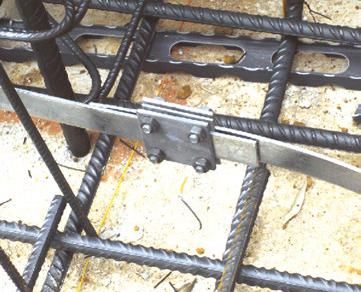
Collegamento ferri d’armatura Dispersori a picchetto
7 Connection reinforcing rods 5 Earth electrode
pag. 277 pag. 271
Pozzetti
6 Earth pits
pag. 275
1
2
6 3
4 7
2 1A
Nota:
3 Conduttori ed accessori devono
2A
essere di materiale omogeneo: acciaio
/ acciaio; rame / rame o ottone /
1 acciaio rivestito di rame.
1 Notes:
5 3 Conductor and accessories must be
made from the same material:
2 steel - steel, copper - copper / brass.
The interposition of bimetal plates is also
6 recommended.
6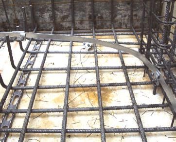
SISTEMI PER IMPIANTI DI TERRA
EARTHING SYSTEMS

RIFERIMENTI NORMATIVI / NORMATIVE REFERENCES
Ci sono diverse Norme e Guide del CEI (Comitato Elettrotecnico Italiano)         The numerous technical standards, developed by the IEC and adopted by the
che si occupano degli impianti di terra. L’impianto in genere è unico e          European Committee for Electrotechnical Standardisation (CENELEC), are
sembrerebbe che la scelta dei componenti potesse essere univoca. In              collectively known as EN 62305. Hundreds of lightning protection specialists
realtà, proprio per la differenziazione delle Norme è bene identificare se       from the 28 different member countries that represent CENELEC contributed
si tratta di un impianto soggetto alla sola applicazione in circuiti di bassa    to the writing of these standards over a period of more than 20 years.
tensione, circuiti di alta tensione oppure impianti per la protezione contro
i fulmini. Nelle “Note Tecniche” vengono presentate diverse tabelle per le       CEI (Comitato Elettrotecnico Italiano) is the Italian Institute in charge of
diverse applicazioni. Le Norme e Leggi di riferimento più importanti sono:       standardization and unification in the electrical, electronic and
                                                                                 telecommunications field. Earthing systems, which therefore come under the
- Norma CEI 64-8, 7a edizione 2012 “Impianti elettrici utilizzatori a            jurisdiction of CEI, should be regulated according to one set of rules. However,
  tensione nominale non superiore a 1000 V in corrente alternata e a             legislation differentiates between low and high voltage circuits and systems
  1500 V in corrente continua”.                                                  for the protection against lightening. Technical notes tables specify which
                                                                                 components should be used for each purpose. The main Rules and Regulations
- CEI EN 62305-3 Protezione contro i fulmini “Danno materiale alle               are:
  strutture e pericolo per le persone"
                                                                                 - CEI 64-8 Electrical systems at a rated voltage not exceeding 1000 V c.a. and
- CEI EN 50522 “Messa a terra degli impianti elettrici a tensione superiore        1500 V d.c. (CENELEC-HD 60364-5-54; IEC 60364-1).
  a 1 kV in c.a. (CEI 99-3).
                                                                                 - CEI EN 62305-3 Protection Against Lightning; Physical damage to structures
- DM 22 gennaio 2008, n. 37 “Riordino delle disposizioni legislative in            and life hazard.
  materia di attività di installazione degli impianti elettrici negli edifici.
                                                                                 - CEI EN 62305-1 Protection Against Lightning; General Principle.
- DPR 462/01 “Procedimento per la denuncia di installazioni e dispositivi
  di protezione contro le scariche atmosferiche, di dispositivi di messa a       - CEI 64-12 Guidelines for the construction of earthing systems for residential
  terra di impianti elettrici e di impianti elettrici pericolosi”.                 and commercial buildings.
- D.Lgs 9 aprile 2008, n. 81 “Attuazione dell’articolo 1 della Legge 3           - CEI 11-37 Guidelines for the construction of earthing systems where
  agosto 2007, 123 in materia di tutela della salute e della sicurezza nei         consumption is greater than 1 kV (buildings with HV/LV inside).
  luoghi di lavoro”.
                                                                                 - CEI 81-5 Equipment for the protection against lightning.
- Guida CEI 64-12 “Guida per l’esecuzione dell’impianto di terra negli             Part 1: Phasing out connection components (CEI EN 62561-1).
  edifici per uso residenziale e terziario”.
                                                                                 In general it can be assumed that a system for protecting against lightning is
- Guida CEI 11-37 “Guida per l’esecuzione degli impianti di terra nei            also suitable for other applications. The reverse is not true.
  sistemi utilizzatori di energia alimentati a tensione maggiore di 1 kV.
                                                                                 Components for LPSs undergo tests for resistance to environmental corrosion
- Norma CEI 81-5 “Componenti per la protezione contro i fulmini.                 and are also tested with an electrical pulse waveform of 10/350 microseconds.
  Parte 1: Prescrizione per i componenti di connessione (Norma CEI EN
  50164-1 sostituito da CEI EN 62561-1).                                         There are two classes of test:

- CEI EN 62561 Serie da 1 a 7 “Componenti dei sistemi di protezione              - Class "H" = 100kA (10/350).
  contro i fulmini LPSC (Lightning Protection System Components). Si             - Class "M" = 50kA (10/350).
  tratta di adeguamenti della Norma europea EN alla Norma
  internazionale IEC.                                                            Components are chosen according to the desired level of protection and to
                                                                                 expected lightning strike charges.
In generale si può ritenere che un impianto adatto alla protezione contro
i fulmini è adatto anche alle altre applicazioni. Non è vero il contrario.
I componenti per gli LPS vengono provati per resistere all'azione della
corrosione ambientale e con un test elettrico impulsivo con forma d'onda
10/350 µs.
Sono previste due classi di prova:
- Classe "H" = 100 kA (10/350).
- Classe "N" = 50 kA (10/350).
In relazione al livello di protezione ed alle correnti di fulminazione
presunte si scelgono i componenti.
Dal punto di vista applicativo, queste prestazioni si traducono nelle
seguenti applicazioni:
- Per impianti di I/II livello, utilizzare prodotti Classe "H".
- Per impianti di III/IV livello, utilizzare prodotti Classe "N".

                                                                                                                                                               7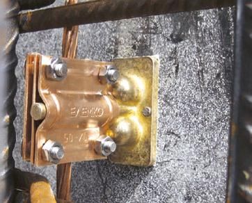
SISTEMI PER IMPIANTI DI TERRA
EARTHING SYSTEMS

NOTE TECNICHE / TECHNICAL NOTES

PREMESSA                                                                                   INTRODUCTION
L’impianto di terra è il piano su cui si costruisce la sicurezza. Non possiamo             An earthing system is the base on which security is built. We cannot strictly say
dire che la sicurezza è legata solamente all’impianto di terra, perché ci                  though that safety can only be achieved with an earthing system; because
sono altri metodi di protezione contro i pericoli di natura elettrica che                  there are other methods related to protection against hazards of electrical
sono altrettanto validi. Una buona terra associata ad un corretto uso dei                  origin that are equally valid. However, a sound earthing system, combined with
collegamenti di equipotenzialità rappresentano la soluzione più utilizzata                 proper use of equipotential bonding connections, is the most popular solution
per raggiungere i migliori livelli di sicurezza.                                           to achieve more guaranteed levels of safety.
In questi ultimi anni abbiamo assistito ad uno sforzo comune tra i                         In recent years regulatory bodies and manufacturers of materials for earthing
normatori ed i costruttori di materiali per impianti di terra, atto ad                     systems have made concerted efforts to find more efficient and affordable
assicurare una risposta tecnica più razionale ed economicamente                            technological solutions which may benefit consumers. Manufacturers have
accettabile per la comunità.                                                               succeeded in producing materials which are consistently resistant to corrosion
I costruttori hanno prodotto materiali più resistenti alle corrosioni con                  for their intended life expectancy of. The table below indicates the minimum
dimensionamenti logici in relazione alla durata dell’impianto. La tabella                  requirements for the main components used to build an earthing system
sotto riportata mette in evidenza le caratteristiche minime dei principali                 according to regulation contained in CEI 64-8; 7th edition 2012.
componenti da utilizzarsi per realizzare un impianto di terra secondo le
norme CEI 64-8; 7a edizione 2012.                                                          Table - Minimum dimensions, in relation to corrosion and mechanical
                                                                                           strength, for foundation earth electrodes made with commonly used
Tabella - Dimensioni minime per i dispersori intenzionali realizzati                       materials.
con i materiali comunemente usati dal punto di vista della corrosione
e della resistenza meccanica.

                                                                                                        Dimensione minima / Minimum dimensions

    Materiale        Superficie              Tipo di dispersori                               Corpo / Core                               Rivestimento / guaina - Plating / sheath
    Material          Surface                Type of electrode             Diametro             Sezione               Spessore            Valore singolo         Valore medi
                                                                           Diameter           Cross-Section           Thickness            Single value          Average value
                                                                              mm                  mm2                   mm                     µm                     µm
                                       Piattina / Strip (b)                                        90                     3                     63                    70
                                       Profilato / Profile (inc. plates)                           90                     3                     63                    70
                                       Tubo / Pipe                            25                                          2                     47                    55
                                       Barra tonda per picchetto
                 Zincato a caldo                                              16                                                                 63                    70
                                       Round bar for earth electrode
                Hot galvanized steel
                                       Tondo per dispersore
                                       orizzontale
                                                                              10                                                                                       50
                                       Round wire for horizontal
                                       earth electrode

     Acciaio                        Tondo per dispersore
      Steel     Guaina di piombo(a) orizzontale
                                                                              8                                                                1000
                 With lead sheath Round wire for horizontal
                                    earth electrode
                Con guaina di rame
                      estrusa        Barra tonda per picchetto
                                                                              15                                                               2000
                With extruded copper Round bar for earth rod
                       sheath
                Con guaina di rame
                   elettrolitica    Barra tonda per picchetto
                                                                             14,2                                                                90                   100
                  With electrolytic Round bar for earth rod
                  copper sheath
                                       Piattina / Strip                                            50                     2
                                       Tondo per dispersore
                                       orizzontale
                       Nudo                                                                       25 (c)
                                       Round wire for horizontal
                       Bare            earth electrode
                                       Corda / Stranded cable               1,8 (d)                25
     Rame
                                       Tubo / Pipe                           20                                           2
     Copper
                     Stagnato
                                       Corda / Stranded cable               1,8 (d)                25                                            1                      5
                      Tinned
                      Zincato
                                       Piattina / Strip                                            50                     2                      20                    40
                  Zinc Galvanized
                Guaina di piombo(a) Corda / Stranded cable                  1,8 (d)                25                                          1000
                 With lead sheath Filo tondo / Round wire                                          25                                          1000
a: Non idoneo per posa diretta in calcestruzzo. Si raccomanda di non usare il piombo per ragioni di inquinamento.
   Not suitable for direct embedding in concrete. Use of lead is not recommended due to environmental reasons.
b: Piattina, arrotondata o tagliata con angoli arrotondati. / Strip, rolled or cut with rounded edges.
c: In condizioni eccezionali, dove l'esperienza mostra che il rischio di corrosione e di danno meccanico è estremamente basso, si può usare 16 mm2.
   In extreme conditions where experience shows that the risk of corrosion and mechanical damage is extremely low 16 mm2 can be used.
d: Per fili singoli. / For single wire.
Nota: Gli stessi componenti sono utilizzabili anche per impianti di terra                  Note: The same components are also used for earthing system exceeding
superiori a 1 kV c.a. (CEI EN 50522).                                                      1 kV AC (CEI EN 50522).

8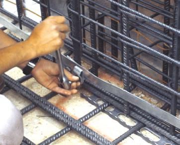
SISTEMI PER IMPIANTI DI TERRA
EARTHING SYSTEMS

NOTE TECNICHE / TECHNICAL NOTES

L’IMPIANTO DI TERRA E LA LEGGE 37/08 (EX 46/90)                                   MATERIALS
Da quando è entrata in vigore la legge 46/90 (oggi 37/08), ed in particolare      It is possible to construct earthing systems of all kinds and in accordance with
il regolamento di attuazione DPR 447/91, ricorre spesso la domanda se è           local regulations when using materials supplied by us.
obbligatorio o meno realizzare l’impianto di terra. Diciamo che forse è più       In addition to traditional products we also have a wide range of accessories to
semplice dire quando non è obbligatorio l’impianto di terra. L’impianto di        suit specific purposes: such as deep electrodes, modular extendable plates,
terra può non essere realizzato in tutti gli edifici con sola destinazione ad     equipotential bonding bar, and non-standard fittings.
                                                                                  When using items which are designed and manufactured for specific use it is
uso abitativo che avevano impianti elettrici costruiti prima del marzo
                                                                                  possible to achieve a reduction in installation time and obtain higher reliability
1990. In tutti gli altri casi l’impianti di terra è obbligatorio.
                                                                                  for the earthing system.

MATERIALI
Utilizzando i materiali da noi forniti è possibile realizzare impianti di terra
di ogni tipo, nel rispetto della regolamentazione nazionale ed europea CEI
EN.
In particolare, la norma CEI 62305 serie 1-2-3-4, 2a edizione, richiede che i
componenti (LPSC) da utilizzare per l'installazione di impianti contro i
fulmini siano conformi alla serie di norme CEI EN 62561 come indicato
nelle tabelle successive.
Accanto ai manufatti tradizionali vengono presentati accessori per
applicazioni specifiche quali dispersori di profondità modulari
prolungabili, piastre per i collegamenti equipotenziali, raccorderie
speciali.
L’uso di questi articoli progettati e realizzati per lo specifico impiego cui
sono destinati consente una riduzione dei tempi di installazione ed il
raggiungimento della massima affidabilità per l’impianto.

                                                                                                                                                                  9
SISTEMI PER IMPIANTI DI PARAFULMINE - LPS ESTERNI
LIGHTNING PROTECTION SYSTEMS - EXTERNAL LPS
ESEMPIO DI IMPIANTO PARAFULMINE ESTERNO E DI TERRA
EXAMPLE OF AN EXTERNAL LIGHTNING PROTECTION AND EARTHING SYSTEM
SCELTA DEI COMPONENTI CHOICE OF COMPONENTS
Esempio di struttura con tetto piano e bordo superiore rivestito in acciaio Example: flat roof building with stainless steel roof border.
Inox.
Note:
Nota: Page number references help identify products suitable for building lightning protection
Le pagine riportate nei riquadri dei prodotti consentono di identificare altri articoli systems different from the example outlined below.
per la realizzazione di impianti parafulmini di strutture con caratteristiche diverse
dall’esempio.
1 Piatto o tondo 7 Morsetti di sezionamento
Tape or round Sectioning clamp
pag. 273 pag. 291
Supporti per tetti Supporti per barre di adduzione
2 8
Roof supports Support for conductor rods
pag. 290 pag. 285
Giunzioni tra barre di adduzio-
Giunzioni ne e tondi / piatti
3 Cross connector clamps 9
Tape and round fasteners for
pag. 283 pag. 283 conductor rods
Supporti per calate Dispersori e accessori
4 Supports for down conductors 10
Earth electrodes and accessories
pag. 285 pag. 268
Aste di captazione Piatti e tondi
5 Air termination rods 11
Tape and round
pag. 279 pag. 273
Ancoraggi per captatori / calate
Clamp support for air Piastra per nodo equipotenziale
6 termination rods and down 12
Equipotential bonding bar
pag. 289 conductors pag. 293
Nota:
Conduttori ed accessori devono
essere di materiale omogeneo:
acciaio / acciaio; rame / rame o ottone,
acciaio rivestito di rame, alluminio
rivestito di rame. È utile l'interposizione
di lamine bimetalliche per collegamenti
tra materiali diversi.
Notes:
Conductor and accessories must be
made from the same material:
steel - steel, copper - copper / brass The
interposition of bimetal plates is also
recommended.
10SISTEMI PER IMPIANTI DI PARAFULMINE - LPS ESTERNI
LIGHTNING PROTECTION SYSTEMS - EXTERNAL LPS
RIFERIMENTI NORMATIVI / NORMATIVE REFERENCES
SIMBOLI SUGGERITI DAL TECHNICAL REPORT CENELEC: PICTOGRAM EXPLANATION OF SYMBOLS PROPOSED BY
TR 50469:2005 PER LA PROGETTAZIONE DI IMPIANTI CENELEC TECHNICAL REPORT 50469:2005 FOR THE DESIGN
PARAFULMINE - LPS OF LIGHTNING PROTECTION SYSTEMS
Parti dell’impianto parafulmine: Parts of a LPS:
Simboli / Symbols Descrizione / Description Nome / Remarks
Asta di captazione Caratteristiche aggiuntive indicano i materiali e le misure
Air termination rod or stud Optional character indicates size and material
Conduttore orizzontale (esposto) Può essere utilizzato anche per i verticali
Horizontal conductor (exposed) Can also be used for vertical conductors
Conduttore di terra orizzontale
Horizontal earth conductor
Spessori delle linee 2 o 3 volte lo spessore delle linee di rappresentazione dell’edificio.
Conduttore orizzontale (nascosto senza contatto di terra) Caratteristiche aggiuntive indicano i materiali e le misure.
Horizontal conductor (hidden without earth contact) Line thickness about 2 or 3 times the line thickness of the building.
Optional character indicates size and material.
Conduttore per terra di fondazione
Foundation earth electrode
Simbolo generale di terra Caratteristiche aggiuntive indicano le misure, tipo e materiale dell'elettrodo.
Earth electrode (general) Optional character indicates size and material of electrode.
Terra con connessioni accessibili Caratteristiche aggiuntive indicano le misure e tipo dell'elettrodo e cassetta.
Earth electrode with accessible connection Optional character indicates size and material of electrode and enclosure.
Picchetto verticale Caratteristiche aggiuntive indicano le misure, tipo e materiale dell'elettrodo.
Vertical earth electrode Optional character indicates size and material of electrode.
Caratteristiche aggiuntive indicano il tipo di connessione o terminale esempio,
Collegamenti e terminali morsetto,avvitato, saldato, etc..
Conductor connection or termination Optional character indicates type of connection or termination, eg. clamp, bolt, welded
etc..
Punto di misura
Test joint
Conduttori in direzione verso l’alto
Conduttori in direzione verso il basso
Conduttori in direzione verso alto e basso
Conductor leading upwards
Conductor leading downwards
Conductor leading upwards and downwards
Conduttore di equipotenzialità Specificare il tipo di conduttore.
Bonding conductor Conductor type to be specified.
Conduttore di equipotenzialità flessibile
Flexible bonding conductor
Nodo di equipotenzialità
Earth bar or equipotential bonding bar
Spinterometri di isolamento Per spinterometri speciali occorrono marchiature aggiuntive per esempio “EX”.
Isolating spark gap For non-standard spark gap additional marking necessary, for example with symbol “Ex”
SPD - Limitatori Caratteristiche aggiuntive dovrebbero essere indicate, tipo di limitatore, etc..
Surge protection device Optional character could indicate the type of protection device.
11SISTEMI PER IMPIANTI DI PARAFULMINE - LPS ESTERNI
LIGHTNING PROTECTION SYSTEMS - EXTERNAL LPS
RIFERIMENTI NORMATIVI / NORMATIVE REFERENCES
MATERIALI PER LA REALIZZAZIONE DI LPS ESTERNI MATERIALS EMPLOYED TO DESIGN ON EXTERNAL LPS
I materiali utilizzati per impianti di terra soggetti all’applicazione della sola Earthing system materials employed according to standards set out in
Norma CEI 64-8 (7a edizione 2012) sono diversi dai materiali utilizzati nei CEI 64-8; V2 are different from materials used for LPS electrodes as shown in
dispersori per LPS come evidenziato nelle tabelle seguenti. the following tables.
Morsetti e conduttori devono essere conformi alla Norma EN 50164 e Clamps and conductors must comply with standards set out in EN 50164 and
CEI EN 62561-2 e dimensionati per le correnti di fulmine previsti dal livello their dimensions must be in proportion to the level of protection required
di protezione nel punto di installazione. against lightning strikes at the point of installation.
Tabella - Materiali, configurazioni e sezioni minime dei conduttori e Table - Materials, configurations and minimum cross-sectional area of
delle aste del sistema di captatori, dei picchetti e dei conduttori air-terminal conductors, air termination rods, earth lead-in rods and
delle calate(a) down-conductors (a)
Materiale Configurazione Sezione minima (a) Commento
Material Configuration Cross-sectional area (a) Recommended dimensions
mm2
Nastro massiccio / Solid tape ≥ 50 2 mm di spessore. / 2 mm thickness.
Tondo massiccio / Solid round (d) ≥ 50 8 mm di diametro. / 8 mm diameter.
Rame / Copper
Rame stagnato / Tin plated copper (b) 1,7 mm di diametro di ciascuno cond. elementare. (f)
Cordato / Stranded (d) (g) ≥ 50
1,7 mm diameter of each strand. (f)
Tondo massiccio / Solid round ≥ 176 15 mm di diametro. / 15 mm diameter.
Nastro massiccio / Solid tape ≥ 70 3 mm di spessore. / 3 mm thickness.
Alluminio Tondo massiccio / Solid round ≥ 50 8 mm di diametro. / 8 mm diameter.
Aluminium 1,63 mm di diametro di ciascuno cond. elementare.
Cordato / Stranded (g) ≥ 50
1,63 mm diameter of each strand.
Lega di alluminio ramata (e)
Tondo massiccio / Solid round ≥ 50 8 mm di diametro. / 8 mm diameter.
Copper coated Aluminum alloy (e)
Nastro massiccio / Solid tape ≥ 50 2,5 mm di spessore. / 2,5 mm thickness.
Tondo massiccio / Solid round ≥ 50 8 mm di diametro. / 8 mm diameter.
Lega di alluminio
Aluminum alloy 1,7 mm di diametro di ciascuno cond. elementare.
Cordato / Stranded (g) ≥ 50
1,7 mm diameter of each strand.
Tondo massiccio / Solid round ≥ 176 15 mm di diametro. / 15 mm diameter.
Nastro massiccio / Solid tape ≥ 50 2,5 mm di spessore. / 2,5 mm thickness.
Tondo massiccio / Solid round ≥ 50 8 mm di diametro. / 8 mm diameter.
Acciaio zincato a caldo
Hot dipped galvanized steel 1,7 mm di diametro di ciascuno cond. elementare.
Cordato / Stranded (g) ≥ 50
1,7 mm diameter of each strand.
Tondo massiccio / Solid round ≥ 176 15 mm di diametro. / 15 mm diameter.
Acciaio ramato (e) Tondo massiccio / Solid round ≥ 50 8 mm di diametro. / 8 mm diameter.
Copper coated steel (e) Nastro massiccio / Solid tape ≥ 50 2,5 mm di spessore. / 2,5 mm thickness.
Nastro massiccio / Solid tape ≥ 50 2 mm di spessore. / 2 mm thickness.
Tondo massiccio / Solid round ≥ 50 8 mm di diametro. / 8 mm diameter.
Acciaio inossidabile (c)
Stainless steel (c) 1,7 mm di diametro di ciascuno cond. elementare.
Cordato / Stranded (g) ≥ 70
1,7 mm diameter of each strand.
Tondo massiccio / Solid round ≥ 176 15 mm di diametro. / 15 mm diameter.
NOTE: Per l'applicazione dei conduttori, vedere IEC 62305-3. / For the application of the conductors, see IEC 62305-3.
(a) Tolleranza di produzione: -3%.
Manufacturing tolerance: -3%.
(b) Rivestimento minimo per zincatura a caldo o deposito elettrolitico di 1 µm.
Hot dipped or electroplated; minimum thickness coating of 1 µm.
(c) Cromo ≥ 16%; nichel ≥ 8%; carbonio ≤ 0,08%.
Chromium ≥ 16%; nickel ≥ 8%; carbon ≤ 0,08%.
(d) In alcune applicazioni dove la resistenza meccanica non è un requisito essenziale, i 50 mm2 (8 mm di diametro) possono essere ridotti a 25 mm2 (6 mm di diametro).
50 mm2 (8 mm diameter) may be reduced to 25 mm2 (6 mm diameter) in certain applications where mechanical strengt is not an essential requirement.
(e) Lo spessore della copertura di rame non può essere inferiore a 70 µm con 99,9% contenuto di rame.
Minimum 70 µm radial copper coating of 99,9% copper content.
(f) In alcuni paesi può essere utilizzato il diametro elementare di 1,14 mm.
In some countries 1,14 mm diameter of each strand may be used.
(g) La sezione trasversale del conduttore è determinato misurando la resistenza in accordo a IEC 60228.
The cross sectional area of stranded conductors is determined by the resistance of the conductor according to IEC 60228.
12SISTEMI PER IMPIANTI DI PARAFULMINE - LPS ESTERNI
LIGHTNING PROTECTION SYSTEMS - EXTERNAL LPS
RIFERIMENTI NORMATIVI / NORMATIVE REFERENCES
TABELLA - MATERIALE, CONFIGURAZIONE E SEZIONE TABLE - MATERIAL, CONFIGURATION AND CROSS SECTIONAL
TRASVERSALE DI DISPERSORI AREA OF EARTH ELECTRODES
Materiali Configurazione Sezione trasversale / cross sectional area (a) Commento
Material Configuration Recommended dimensions
Diametro picchetto Conduttore di Terra Piastra
Earth rod diameter Earth Conductor Earth plate
mm mm2 cm2
Rame / Copper Cordato / Stranded ≥ 50 (i) 1,7 mm di diametro di ciascuno cond. elementare.
Rame stagnato / Tin plated copper 1,7 mm diameter of each strand.
(f)
Tondo massiccio / Solid round ≥ 50 8 mm di diametro. / 8 mm diameter.
Nastro massiccio / Solid tape ≥ 50 2 mm di spessore. / 2 mm thickness.
Tondo massiccio / Solid round ≥ 176 15 mm di diametro. / 15 mm diameter.
Tubo / Pipe ≥ 110 20 mm di diametro con 2 mm di spessore della parete.
20 mm diameter with 2 mm wall thickness
Piastra massiccia / Solid plate ≥ 2500 500 mm x 500 mm con 1,5 mm di spessore. (g)
500 mm x 500 mm with 1,5 mm thickness (g)
Piastra a graticcio / Lattice plate (g) ≥ 3600 600 mm x 600 mm costituito da 25 mm x 2 mm per la
sezione del nastro o 8 mm di diametro per il conduttore
tondo.
600 mm x 600 mm consisted of 25 mm x 2 mm section for
tape or 8 mm diameter for round conductor
Acciaio zincato a caldo Tondo massiccio / Solid round ≥ 78 10 mm di diametro. / 10 mm diameter.
Hot dipped galvanized steel Tondo massiccio / Solid round ≥ 150 (b) 14 mm di diametro. / 14 mm diameter.
25 mm di diametro con 2 mm di spessore della parete.
Tubo / Pipe ≥ 140 (b)
25 mm diameter with 2 mm wall thickness
Nastro massiccio / Solid tape ≥ 90 3 mm di spessore. / 3 mm thickness.
500 mm x 500 mm con 3 mm di spessore.
Piastra massiccia / Solid plate ≥ 2500
500 mm x 500 mm with 3mm thickness.
600 mm x 600 mm costituito da 30 mm x 3 mm per la
sezione del nastro o 10 mm di diametro per il
Piastra a graticcio / Lattice plate (d) ≥ 3600 conduttore tondo.
600 mm x 600 mm consisted of 30 mm x 3 mm section for
tape or 10 mm diameter for round conductor
Profilato / Profile (e)
3 mm di spessore. / 3 mm thickness.
Acciaio 1,7 mm di diametro di ciascuno cond. elementare.
Bare steel Cordato / Stranded ≥ 70
1,7 mm diameter of each strand.
Tondo massiccio / Solid round ≥ 78 10 mm di diametro. / 10 mm diameter.
Nastro massiccio / Solid tape ≥ 75 3 mm di spessore. / 3 mm thickness.
Acciaio ramato (c) 14 mm di diametro, con rivestimento minimo
Copper coated steel (c) di 250 µm in rame, con 99,9% contenuto di rame.
Tondo massiccio / Solid round ≥ 150 (h) 14 mm diameter, if 250 µm minimum radial copper
coating, with 99,9% copper content.
8 mm di diametro, con rivestimento minimo
di 250 µm in rame, con 99,9% contenuto di rame.
Tondo massiccio / Solid round ≥ 50 8 mm diameter, if 250 µm minimum radial copper coating,
with 99,9% copper content.
10 mm di diametro, con rivestimento minimo
di 70 µm in rame, con 99,9% contenuto di rame.
Tondo massiccio / Solid round ≥ 78 10 mm diameter, if 70 µm minimum radial copper coating,
with 99,9% copper content.
3 mm di spessore, con rivestimento minimo
di 70 µm in rame, con 99,9% contenuto di rame.
Nastro massiccio/ Solid tape ≥ 90 3 mm thickness, if 70 µm minimum radial copper coating,
with 99,9% copper content.
Acciaio inossidabile Tondo massiccio / Solid round ≥ 78 10 mm di diametro. / 10 mm diameter.
Stainless steel Tondo massiccio / Solid round ≥ 176 (h) 15 mm di diametro. / 15 mm diameter.
Nastro massiccio/ Solid tape ≥ 100 2 mm di spessore. / 2 mm thickness.
NOTE: Per l'applicazione dei conduttori, vedere IEC 62305-3. / For the application of the conductors, see IEC 62305-3.
(a) Tolleranza di produzione: -3%. / Manufacturing tolerance: -3%.
(b) Filettature, se esistenti, devono essere lavorate prima della zincatura. / Threads, where utilized, shall be machined prior to galvanizing.
(c) La ramatura dovrà essere connessa intrinsecamente all'acciaio, lo spessore della protezione può essere misurato con uno strumento elettronico per lo spessore dei rivestimenti.
The copper shall be intrinsically bonded to the steel. The coating can be measured using an electronic coating measuring thickness instrument.
(d) Piastre a graticcio devono avere una lunghezza minima degli elementi di 4,8 m. / Lattice plate constructed with a minimum total conductor lenght of 4,8 m.
(e) Differenti profili sono ammessi con sezioni trasversali minimi di 290 mm2, spessore 3 mm, es. dispersori a croce.
Different profiles are permitted with a cross sectional area of 290 mm2 and minimum thickness of 3 mm, e.g. cross profile.
(f) Rivestimento minimo di zincatura a caldo o deposito elettrolitico di 1 µm. / Hot dipped or electroplated; minimum thickness coating of 1µm.
(g) In alcuni paesi, la sezione trasversale può essere ridotta a ≥ 1800 cm2 e spessore ≥ 0,8 mm.
In some countries, the cross sectional area may be reduced to ≥ 1800 cm2 and thickness to ≥ 0,8 mm.
(h) In alcuni paesi, la sezione trasversale può essere ridotta a 125 mm2. / In some countries, the cross sectional area may be reduced to 125 mm2.
(i) La sezione trasversale del conduttore è determinato misurando la resistenza in accordo a IEC 60228.
The cross sectional area of stranded conductors is determined by the resistance of the conductor according to IEC 60228.
13SISTEMI PER IMPIANTI DI PARAFULMINE - LPS ESTERNI
LIGHTNING PROTECTION SYSTEMS - EXTERNAL LPS
SUGGERIMENTI PER LA REALIZZAZIONE DI UN IMPIANTO PARAFULMINE A MAGLIA
RECOMMENDATIONS FOR IMPLEMENTING AN LPS WITH AN AIR TERMINATION MESH
PREMESSA INTRODUCTION
Prescindendo dal calcolo di probabilità di fulminazione attraverso il quale When the need arises to install a lightning protection system, according to
si definisce la necessità o meno di realizzare l’impianto di parafulmine probabilistic models, the key elements providing protection against lightning
(LPS), gli elementi fondamentali di una protezione contro le scariche are: the air termination mesh, the down conductors and the earth electrode.
atmosferiche sono: gli organi di captazione (maglia di captazione), le
calate ed il dispersore. AIR TERMINATION MESH
MAGLIA DI CAPTAZIONE An appropriate level of protection is calculated according to the type of
building and the likelihood of a lightning strike (IEC 62305-2).
Si deve definire un opportuno livello di protezione dell’impianto in base al In this respect CEI rules are also applied to classify systems according to the
tipo di edificio ed alla probabilità di fulminazione (norme CEI 81-10/2). levels of protection they afford as shown in Table 1 (IEC 62305-1).
A tale proposito le stesse norme CEI classificano gli impianti secondo i Once the level of protection, and therefore the efficiency of protection, is
livelli di protezione riportati in Tabella 1 (CEI 81-10/1). calculated the choice of mesh size can be easily derived: see Table 2.
Definito il livello di protezione e quindi l’efficienza dell’impianto di
protezione, la scelta delle dimensioni delle maglie è immediata: vedere
Tabella 2 (CEI 81-10/3).
TABELLA 1 / Table 1
Livello di protezione Efficienza (*) Corrente di fulmine (kA)
Level of protection Efficiency (*) Lightning charge (kA)
I ≤ 0,99 200
II ≤ 0,97 150
III ≤ 0,91 100
IV ≤ 0,84 100
(*) Per efficienza si intendono i valori riferiti alle probabilità di superamento delle correnti di
fulmine.
The efficency of a protection mesure is assumed equal to the probability with which lightning current
parameters are insaide such range. Esempio:
Livello IV lato maglia:
20 m max
TABELLA 2 / TABLE 2 A = 28 m; B = 25 m; H = 15 m.
Livello di protezione Dimensioni massime del lato della maglia in metri Lunghezza totale del captatore:
Level of protection Maximum length of air termination mesh 28 x 3 + 25 x 3 = 159 m.
IV 20 Example:
Level IV length of mesh:
III 15
20 m maximum
II 10 A = 28 m; B = 25 m; H = 15 m.
Total length of the air termination mesh:
I 5
28 x 3 + 25 x 3 = 159 m.
Con riferimento alla figura si determina la geometria della maglia e la sua The shape of the mesh and its length are determined with reference to the
lunghezza: vedere esempio in Fig. 1. shape and dimensions of the building: see example in Figure 1.
Nel posizionamento delle maglie si devono tener presenti i seguenti When positioning the mesh the following must be kept in mind:
suggerimenti: - conductors should be arranged on the outer edges of the building;
- disporre i conduttori sugli spigoli perimetrali dell’edificio; - the mesh thus created should not extend beyond that what is shown in
- le maglie così create non devono avere dimensioni superiori a quanto Table 2.
indicato nella Tabella 2.
The minimum size of the cross-section of the air termination elements must be
La sezione minima degli elementi di captazione dovrà essere di almeno at least 50 mm2 for galvanized steel round, and 50 mm2 (2.5 mm) for galvanized
50 mm2 per tondi in acciaio zincato, e di 50 mm2 (spessore 2,5 mm) per steel tape.
piatti in acciaio zincato. The mesh supports should be spaced approximately 1 m from each other.
I supporti delle maglie devono essere distanziati di 1 m circa gli uni dagli altri. - Metal elements on the roof must be connected to the mesh.
- I corpi metallici del tetto devono essere collegati alla maglia. - Building elements projecting out of the roof (eg. chimneys) must be
- I volumi che fuoriescono dal tetto (es. camini) devono essere protetti protected with air termination rods so that the cone of protection covers the
con un’asta di captazione posizionata in modo che il suo cono di above mentioned volume (IEC 62305-3).
protezione copra detto volume (CEI 81-10/3). - Metal parts susceptible to changes such as: gutters, decorations, railings,
- Le parti metalliche suscettibili a modifiche quali: grondaie, ornamenti, cannot be used as a natural component, but must be regarded as pieces of
ringhiere, non possono essere utilizzate come componenti naturali, ma metal and therefore must be connected to the mesh.
dovranno essere considerate come corpi metallici e quindi collegate alla - Metal sheet roofing can be used as sensors provided that electrical
maglia. continuity is verified. If the client accepts that in the event of lightning
- Le coperture metalliche in lamiera possono essere utilizzate come perforation to the metal sheet will occur, then the thickness of the metal
captatori purché sia verificata la continuità elettrica; se il committente cover, copper or steel, must be at least 0.5 mm. If perforation of the metal
accetta l’eventuale perforazione in caso di fulminazione, lo spessore cover is not contemplated, the thickness should be at least 4 mm for steel
della copertura metallica, in rame o acciaio, deve essere di almeno 0,5 and 5 mm for copper.
mm. Nel caso non sia ammessa la perforazione della copertura, lo
spessore dovrà essere di almeno 4 mm per l’acciaio e di 5 mm per il
rame.
14SISTEMI PER IMPIANTI DI PARAFULMINE - LPS ESTERNI
LIGHTNING PROTECTION SYSTEMS - EXTERNAL LPS
SUGGERIMENTI PER LA REALIZZAZIONE DI UN IMPIANTO PARAFULMINE A MAGLIA
RECOMMENDATIONS FOR IMPLEMENTING AN LPS WITH AN AIR TERMINATION MESH
CALATE DOWN CONDUCTORS
- Prevedere almeno due calate quando l’LPS non è isolato. Se l’LPS è - Provide at least two down conductors if an LPS is not isolated. Conversely,
isolato occorre prevedere una calata per ogni sostegno perimetrale a down conductor for each support of the perimeter of the mesh must be
della maglia. provided for when an LPS is isolated.
- E’ consigliabile prevedere una calata ed eventualmente un anello - It is advisable to provide for a down conductor, and possibly a middle ring,
intermedio tenendo conto della Tabella 3. as shown in Table 3.
- Le parti metalliche suscettibili a modifiche, ad esempio i pluviali, non - The metal parts susceptible to changes, such as drains, cannot be used as
possono essere utilizzati come calate naturali, ma come corpi metallici. natural conductors and therefore must be regarded as pieces of metal.
- L’inserimento di più calate e di anelli di interconnessione consente di - The inclusion of multiple down conductors and rings of interconnection can
ridurre il numero di collegamenti equipotenziali in quanto si riducono reduce the number of equipotential connectors as the distance security 's' is
le distanze di sicurezza «s». reduced.
Questo parametro deve essere definito in fase progettuale dell’impianto This parameter must be calculated during the planning phase of the LPS
parafulmine (LPS esterno). (external).
- La sezione minima delle calate è quella indicata in Tabella 4. - The minimum section of the conductors is shown in Table 4.
- Per evitare precoci corrosioni è consigliabile distanziare le calate dai - To prevent premature corrosion it is advisable to provide space between the
muri con idonei supporti. down conductors and the walls, using appropriate supports.
- I supporti per l’ancoraggio delle calate devono essere distanziati di - Supports for anchoring the down conductors must be spaced at least 1 m
almeno 1 m gli uni dagli altri. from each other.
- Le calate possono essere intubate o messe sotto intonaco. - The conductors may be ducted or plastered over.
- Ogni calata deve essere munita di apposito morsetto di sezionamento. - All down conductors must be provided with appropriate equipotential
- Dopo il morsetto di sezionamento è consigliabile, nella parte interrata, bonding bars.
l’utilizzo di idonee barre di adduzione al fine di migliorare la resistenza - The use of appropriate bonding bars, to be positioned after the equipotential
meccanica del LPS e la corrosione del terreno che nei primi 50 cm è bonding bar in the ground, is recommended in order to improve the
particolarmente aggressiva. mechanical resistance of a LPS and reduce corrosion at ground level, which
is particularly aggressive in the top 50 cm.
Tabella 3 / Table 3 Tabella 4 / Table 4
Classe LPS Distanze tipiche Materiale Dimensioni
Class of LPS Standard distances Material Dimensions
Rame o Rame Stagnato: Livello I/Level I
I 10 m Copper or tinned copper:
Livello II/Level II
• Nastro / Spessore
II 10 m Tape/thickness 50 mm2 / 2 mm
• Corda / Diam. per filo
III 15 m Stranded/diameter 50 mm2 / 1,7 mm Livello III - IV/Level III - IV
Acciaio Zincato:
IV 20 m Galvanized steel:
• Nastro / Spessore Lunghezza minima di elementi del dispersore in
Tape/thickness 50 mm2 / 2,5 mm
funzione dei livelli di protezione.
• Tondo / Diametro I livelli III e IV sono indipendenti dalla resistività del
Stranded/diameter 50 mm2 / 8 mm suolo.
The minimum lenghts of horizontal electrodes shown in
the figure.
Protection level III and IV are indipendent of the soil
resistivity.
DISPERSORI EARTHING ELECTRODE
- Se l’impianto di terra è già stato realizzato ed il valore di Rt è ≤ 10 Ω, è - If an earthing system has already been built and the value of Rt is ≤ 10 Ω, an
sufficiente collegare le calate su detto impianto compatibilmente con la appropriate solution would be to connect the down conductors on that system in
geometria del LPS. a fashion compatible with the shape of the LPS.
- La norma CEI 81-10/3 prevede due tipi di dispersori: - CEI 81-10/3 contemplates two types of earthing electrodes:
• dispersore di tipo A; • Earthing electrode type A;
• dispersore di tipo B. • Earthing electrode type B.
- Tipo A ad elementi singoli (un elemento per ogni calata) verticali o - Type A is made up of single elements (one element for each down conductor)
orizzontali. Per il dimensionamento del singolo dispersore, consultare vertical or horizontal. For the dimensions of the single earthing electrode,
il diagramma in Figura 2 della norma CEI 81-10/3. see the diagram in Figure 2 of the IEC 62305-3.
In questo diagramma sono riportate le lunghezze l1 in funzione della This diagram shows the lengths l1 in relation to the resistivity of the soil and
resistività del suolo e del livello di protezione. the level of protection required.
- Tipo B ad anello interrato almeno per l’80% della sua lunghezza e - Type B is composed of a ring buried at least 80% of its length and connected
collegato alle calate. Il dimensionamento è rilevabile sempre dalla to the connectors. The dimensions can also be derived from Rule IEC 62305-
Figura 2 della norma CEI 81-10/3. 3 (Fig. 2). The equivalent radius r of the circle of the ring is calculated using
Il raggio r del cerchio equivalente dell’anello deve essere calcolato con la the formula:
formula:
r=
√ area covered by the building (m2)
π
r=
√ area in pianta della struttura (m2)
π
Se "r" risulterà inferiore a l1 (v. Fig. 2) si dovrà integrare ad ogni calata un
If "r" is less than l1 (Fig. 2) a vertical earthing electrode, whose length is calculated
according to the formula below, should be attached to each down connector:
dispersore verticale di lunghezza lv pari a: I1 - r (calculated)
Iv =
I1 - r (calcolato) 2
Iv = If r is more than l1 it is not necessary to attach it to the earthing electrode.
2 Refer to the pages 8 and 13 for material and dimensions of the earthing electrode.
Se r sarà superiore a l1 non necessiterà alcuna integrazione.
Per le dimensioni dei materiali dei dispersori, consultare le tabelle a pag. 8 e 13.
15SISTEMI PER COLLEGAMENTI EQUIPOTENZIALI
EQUIPOTENTIAL BONDING SYSTEMS
NOTE TECNICHE / TECHNICAL NOTES
EQUIPOTENZIALITÀ EQUIPOTENTIAL BONDING
Possiamo affermare che la sicurezza data dall’impianto di terra è più legata It is fair to say that the security of an earthing system is related to its equipotential
alla sua equipotenzialità che al valore in assoluto della RE. bonding to a larger extent than to the absolute value of RE.
E’ importante che nello stesso impianto ci sia un nodo equipotenziale di It is important that there should be an equipotential node reference for each
riferimento al quale devono fare capo tutti i conduttori di protezione dei earthing system to which all protective conductors of electrical circuits as well as
circuiti elettrici e le connessioni delle masse estranee dell’impianto, e ground connections outside the system and any neutral system TN are linked. As
l’eventuale neutro del sistema TN. Nel quadro elettrico principale di part of the main electrical distribution there must always be an equipotential earth
distribuzione dell’energia deve sempre esistere una piastra equipotenziale di plate. (eg. page 237).
terra (es. pag. 237). It is very often the case that mistakes are made when different material of earthing
Molto spesso accade che nei collegamenti tra le masse estranee si commettano systems are connected together. This results in galvanic currents being generated
degli errori grossolani di interconnessione, generando delle correnti that are extremely damaging and which, in the space of only a few years, can
galvaniche molto dannose che nell’arco di pochi anni producono perforazioni produce perforations of the pipes as well as corrosion of the earth electrodes and
delle tubazioni, corrosione dei dispersori, corrosione dei collegamenti. of the connections.
Un esempio: se partiamo da un nodo equipotenziale con un unico conduttore For example: if an equipotential node with a single copper bonding conductor is
di rame ed andiamo a collegare insieme tubi di acciaio zincato, tubazioni del connected to galvanized steel pipes, copper pipes of the heating system, and so on,
riscaldamento di rame, e così via, creiamo una catena di giunzioni galvaniche a chain of galvanic junctions is created between the different metals. This results in
tra metalli diversi. Il risultato finale sarà una forte corrosione di tutti i an aggressive corrosion of all components containing iron. If different kinds of
componenti ferrosi. connection wires are used it would be useful to utilise a stainless steel or hot-
Se si utilizzano conduttori di collegamento di natura diversa può risultare utile galvanized plate bonding, with holes for the lugs or clamps of brass or nickel plated
l’uso di piastre equipotenziali in acciaio inossidabile o zincato a caldo, con fori brass, to mitigate any galvanic joints.
per i capicorda o con morsetti di ottone o ottone nichelato, per attenuare Equipotential bonding is not always obtained through a direct link. In many cases
eventuali giunzioni galvaniche. it is gained through the interposition of SPD for limitation of overvoltage.
L’equipotenzialità non sempre si ottiene tramite un collegamento diretto, in For example: pipes carrying hazardous fluids, such as gas or petrol, may have in
molti casi l’equipotenzialità si ottiene attraverso l’interposizione di limitatori di proximity of the pumping areas some insulated joints separating the section of
sovratensione. underground pipe subject to cathodic protection. It is not possible to restore direct
Riportiamo alcuni esempi: se abbiamo delle tubazioni che trasportano fluidi continuity for these joints with a wired connection, as this would offset a good part
pericolosi quali gas e benzina, può capitare che lungo la tubazione, nelle zone of the cathodic protection. In such cases it is necessary to insert surge-type spark
di pompaggio, ci siano dei giunti isolanti che separano il tratto di tubazione gaps, explosion-proof or normal type, according to the type of fluid flowing in the
interrata soggetto alla protezione catodica. In questi giunti non è possibile pipe.
ripristinare la continuità direttamente con un collegamento metallico; si Power lines, whether power or signal, are another example of an equipotential
verrebbe ad annullare una buona parte della protezione catodica. In questi bonding connection by way of surge protective devices.
punti, sarà necessario inserire dei limitatori di tensione di tipo spinterometrico, Power lines are in fact "external earthing” with respect to all overvoltage
a prova di esplosione o di tipo normale a seconda che si tratti di un fluido phenomena that develop in the same lines affected by direct or indirect lightning
pericoloso o no come l’acqua o altro. Un altro esempio di collegamento strikes.
equipotenziale tramite limitatori sono le linee elettriche, siano esse di potenza The most easily understood is the power line that feeds a building equipped with
o di segnale. the basic system of external LPS.
Infatti le linee elettriche sono delle «masse estranee» particolari rispetto a tutti The moment the building is struck by the atmospheric discharge the whole earthing
i fenomeni di sovratensione che si sviluppano nelle linee stesse colpite da system and all external earthing raise their potential with reference to the points in
fulminazione diretta o indiretta. the ground placed at a certain distance from the building and to the incoming
Il caso più facilmente comprensibile è costituito dalla linea elettrica che power lines. In order to prevent over-voltage on the line, surge protective devices
alimenta un edificio provvisto di impianto base del parafulmine. having a discharge capacity (IEC 62305-2 and IEC 62305-4) must be installed at the
Nell’istante in cui l’edificio viene colpito dalla scarica atmosferica tutto il point closest to the equipotential bonding.
sistema di terra e tutte le masse estranee alzano il loro potenziale rispetto ai
punti del terreno posti ad una certa distanza rispetto all’edificio e rispetto alle DIMENSIONS OF BONDING CONDUCTORS
linee elettriche entranti.
Per evitare che la sovratensione possa scaricarsi sulla linea è obbligatorio The equipotential connectors needed to bond the external earthing at ground level
installare all’ingresso, nel punto più vicino al nodo equipotenziale, dei are the main ones.
limitatori di sovratensione che abbiano una capacità di scarica idonea These cables serve as the link between the main earthing point and a number of
(CEI 81-10/2 e CEI 81-10/4). external earthing connections.
For these connectors, normative prescribes the following minimum diameters:
DIMENSIONAMENTO DEI CONDUTTORI EQUIPOTENZIALI half of the diameter of the largest protection conductor in the system with a
minimum diameter of 6 mm2 and up to a maximum of 25 mm2 if the bonding
I conduttori equipotenziali necessari per il collegamento delle masse estranee conductor is copper, or if the bonding is made of different materials or has
a livello del terreno sono quelli principali. equivalent conductance.
Tali conduttori svolgono la funzione di collegamento fra collettore principale
di terra ed un certo numero di masse estranee.
Per questi conduttori, la norma prescrive le seguenti sezioni-minime:
metà della sezione del conduttore di protezione di sezione più elevata
dell’impianto, con un minimo di 6 mm2; non è richiesto che la sezione superi
25 mm2 se il conduttore equipotenziale è di rame, o se il conduttore è di
materiale diverso, presenta una sezione di conduttanza equivalente.
16Puoi anche leggere