THOR 123 - MANUALE DI ISTRUZIONE PER TAGLIO PLASMA - INSTRUCTION MANUAL FOR PLASMA CUTTING MACHINE - BETRIEBSANLEITUNG FÜR PLASMA SCHNEIDGERÄT ...
←
→
Trascrizione del contenuto della pagina
Se il tuo browser non visualizza correttamente la pagina, ti preghiamo di leggere il contenuto della pagina quaggiù
6934900010

- MANUALE DI ISTRUZIONE PER TAGLIO PLASMA

- INSTRUCTION MANUAL FOR PLASMA CUTTING
  MACHINE

- BETRIEBSANLEITUNG FÜR PLASMA SCHNEIDGERÄT

              THOR 123

    Info : www.stelgroup.it   - tel. +39 0444 639525

                                                               1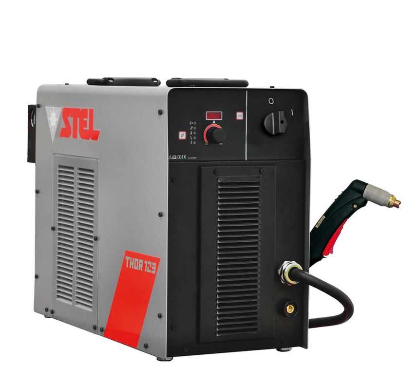
6934900010

                                DECLARATION OF CONFORMITY

                                          According to
                              The Low Voltage Directive 2014/35/EU
                                 The EMC Directive 2014/30/EU
                                The RoHS Directive 2011/65/EU

Type of equipment
Plasma equipment

Type of designation
600403000L - Thor 123

Brand name or trade mark
STEL

Manufacturer or his authorized representatives established within the EEA:
Name, address, phone, website:
STEL s.r.l
Via Del Progresso 59; 36020 Castegnero – Vicenza
Italy
Tel +39-0444-639525 Fax +39-0444-639682 www.stelgroup.it

The following harmonized standard in force within the EEA has been used in the design:
EN 60974-1:2012 Ed.4, Arc welding equipment – Part 1: Welding power sources
EN 60974-10:2007 Ed.2, Arc welding equipment – Part 10: Electromagnetic compatibility (EMC)

Additional information: Restrictive use, Class A equipment, intended for use in locations other than
residential.

By signing this document, the undersigned declares as manufacturer, or the manufacturer’s authorized
representative established within EEA, that the equipment in question complies with the safety requirements
stated above.

Date                                   Signature                               Position

20-04-2016                             Andrea Barocco                          General Manager

                                                                                                          2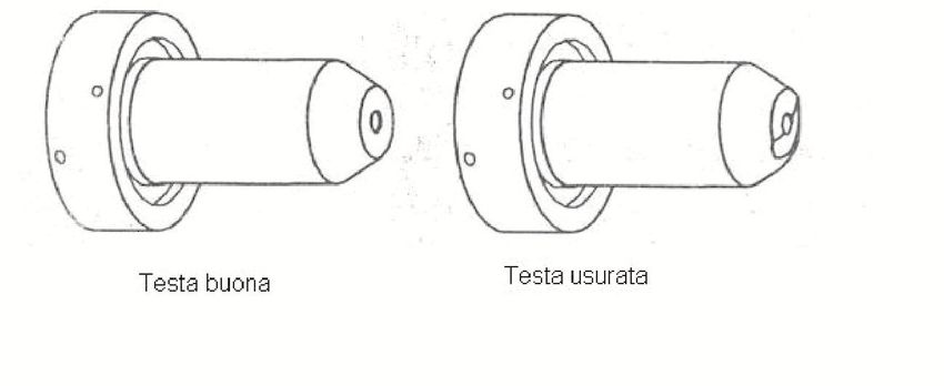
6934900010

SICUREZZE
LO SHOCK ELETTRICO PUÒ UCCIDERE                                                   WARNING
- Disconnettere la macchina dalla rete di
alimentazione prima di intervenire sul generatore.
- Non lavorare con i rivestimenti dei cavi deteriorati.
- Non toccare le parti elettriche scoperte.
- Assicurarsi che tutti i pannelli di copertura del
generatore di corrente siano ben fissati al loro posto
quando la macchina è collegata alla rete di
alimentazione.
- Isolate Voi stessi dal banco di lavoro e dal
pavimento (ground): usate scarpe e guanti isolanti.
- Tenete guanti, scarpe, vestiti, area di lavoro, e
questa apparecchiatura puliti ed asciutti.

I CONTENITORI SOTTO PRESSIONE POSSONO
ESPLODERE SE SALDATI.
Quando si lavora con un generatore di corrente:
- non saldare contenitori sotto pressione.
- non saldare in ambienti contenenti polveri o vapori
esplosivi.

LE RADIAZIONI GENERATE DALL’ARCO Dl                           PREVENZIONE INCENDI
SALDATURA POSSONO DANNEGGIARE GLI                             La saldatura produce schizzi di metallo fuso.
OCCHI E PROVOCARE BRUCIATURE ALLA                             Prendere le seguenti precauzioni per evitare incendi:
PELLE.                                                        - assicurarsi un estintore nell’area di saldatura.
- Proteggere gli occhi ed il corpo adeguatamente.             - allontanare il materiale infiammabile dalla zona
- È indispensabile per i portatori di lenti a contatto        immediatamente vicina all’area di saldatura.
proteggersi con apposite lenti e maschere.                    - raffreddare il materiale saldato o lasciarlo raffreddare
                                                              prima di toccarlo o di metterlo a contatto con materiale
PREVENZIONE USTIONI                                           combustibile
Per proteggere gli occhi e la pelle dalle bruciature e        - non usare mai la macchina per saldare contenitori di
dai raggi ultravioletti:                                      materiale potenzialmente infiammabile. Questi
- portare occhiali scuri. Indossare vestiti, guanti e         contenitori devono essere puliti completamente prima
scarpe adeguate.                                              di procedere alla saldatura.
- usare maschere con i lati chiusi, aventi lenti e vetri di   - ventilare l’area potenzialmente infiammabile prima di
protezione a norme (grado di protezione DIN 10).              usare la macchina.
- avvisare le persone circostanti di non guardare             - non usare la macchina in atmosfere che contengano
direttamente l’arco.                                          concentrazioni elevate di polveri, gas infiammabili o
                                                              vapori combustibili.
IL RUMORE PUÒ’ DANNEGGIARE L’UDITO.
- Proteggersi adeguatamente per evitare danni.                PREVENZIONE CONTRO SHOCK ELETTRICI
                                                              Prendere le seguenti precauzioni quando si opera con
I FUMI ED I GAS POSSONO DANNEGGIARE LA                        un generatore di corrente:
VOSTRA SALUTE.                                                - tenere puliti se stessi ed i propri vestiti.
- Tenere il capo fuori dalla portata dei fumi.                - non essere a contatto con parti umide e bagnate
- Provvedere per una ventilazione adeguata dell’area          quando si opera con il generatore.
di lavoro.                                                    - mantenere un isolamento adeguato contro gli shock
- Se la ventilazione non è sufficiente, usare un              elettrici. Se l’operatore deve lavorare in ambiente
aspiratore che aspiri dal basso.                              umido, dovrà usare estrema cautela, vestire scarpe e
                                                              guanti isolanti.
IL CALORE, GLI SCHIZZI DEL METALLO FUSO E                     - controllare spesso il cavo di alimentazione della
LE SCINTILLE POSSONO PROVOCARE INCENDI.                       macchina: dovrà essere privo di danni all’isolante. I
- Non saldare vicino a materiali infiammabili.                CAVI SCOPERTI SONO PERICOLOSI
- Evitare di portare con sé qualsiasi tipo di
combustibile come accendini o fiammiferi.                     Non usare la macchina con un cavo di alimentazione
- L’arco di saldatura può provocare bruciature. Tenere        danneggiato;       è      necessario      sostituirlo
la punta dell’elettrodo lontano dal proprio corpo e da        immediatamente.
quello degli altri.                                           - se c’è la necessità di aprire la macchina, prima
                                                              staccare l’alimentazione. Aspettare 5 minuti per
                                                              permettere ai condensatori di scaricarsi. Non

                                                                                                                      3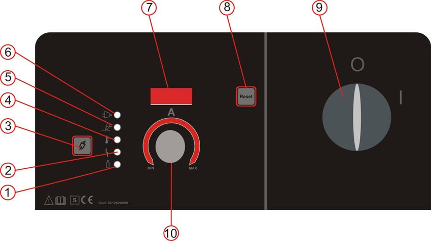
6934900010
rispettare questa procedura può esporre l’operatore a
pericolosi rischi di shock elettrico.
RECLAMI
- non operare mai con il generatore, se la copertura di Reclami per danneggiamento durante il trasporto:
protezione non è al suo posto. Se la Vs. apparecchiatura viene danneggiata durante
- assicurarsi che la connessione di terra del cavo di la spedizione, dovete inoltrare un reclamo al Vs.
alimentazione, sia perfettamente efficiente. spedizioniere.
Reclami per merce difettosa: Tutte le
Questo generatore è stato progettato per essere apparecchiature spedite da STEL sono state
utilizzato in ambiente professionale ed industriale. Per sottoposte ad un rigoroso controllo di qualità. Tuttavia
altri tipi di applicazione contattare il costruttore. Nel se la Vs. apparecchiatura non dovesse funzionare
caso in cui disturbi elettromagnetici siano correttamente, rivolgetevi al Vs. concessionario
individuati è responsabilità dell’utilizzatore della autorizzato.
macchina risolvere la situazione con l’assistenza
tecnica del costruttore. È vietato l’utilizzo e DATI TECNICI
l’avvicinamento alla macchina da parte di persone
portatori di stimolatori elettrici (PACE MAKERS).
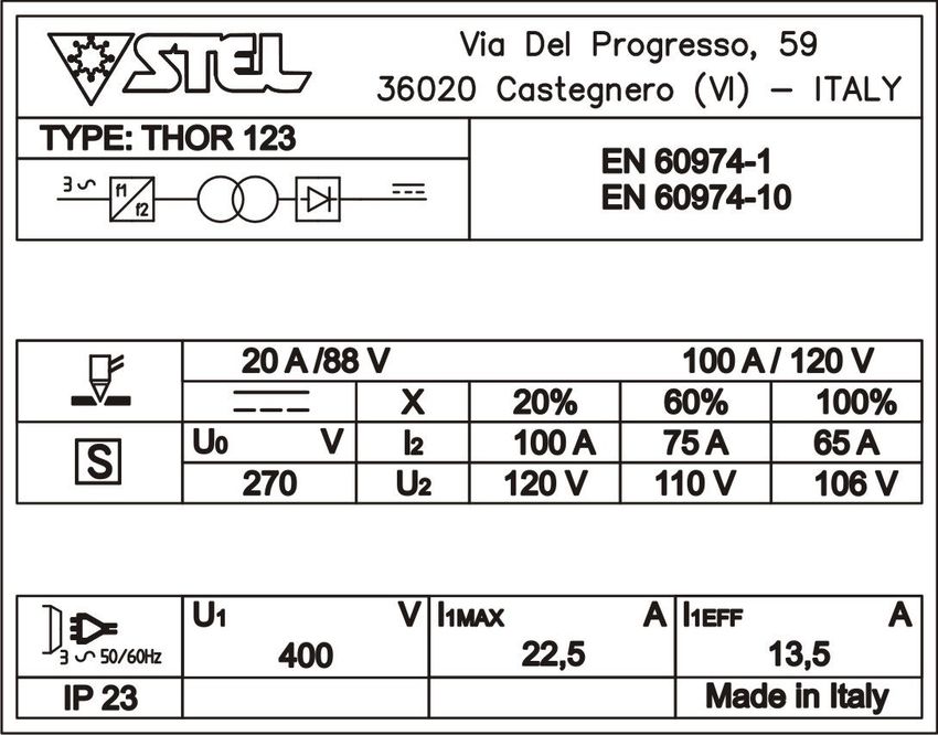
DESCRIZIONE GENERALE A
Il generatore fornisce una corrente continua regolabile
per avere le massime prestazioni di taglio.
Il generatore è stato progettato con le più avanzate
tecnologie per poter offrire i seguenti vantaggi: C
- Peso ridotto per assicurare la massima D
maneggevolezza. B
- La tecnologia ad inverter consente di ottenere un
arco stabile, che assicura un’alta qualità di taglio per
una grande varietà di metalli e di spessori.
- L’arco pilota può perforare metalli verniciati od
arrugginiti.
- L’arco pilota continuo permette di tagliare facilmente
materiali forati; l’arco pilota si trasferisce al pezzo da
tagliare quando la torcia è circa a 3 mm. dalla
superficie di taglio.
- Il potenziometro di regolazione della corrente posto A) IDENTIFICAZIONE
sul pannello frontale, imposta la corrente di taglio. Nome, indirizzo del costruttore
- Il generatore necessita di aria compressa. Tipo generatore
L’aria usata dovrà essere priva di impurità, olio, acqua Identificazione riferita al numero di serie
od altri prodotti inquinanti. Simbolo del tipo di generatore
Riferimento alla normativa di costruzione
RICEVIMENTO B) DATI DI SALDATURA
L’imballo contiene: Simbolo del processo di lavoro
- N. 1 generatore Simbolo per generatori idonei ad operare in ambiente
- N. 1 manuale istruzione
a rischio accresciuto di scossa elettrica.
- N. 1 cavo massa
Simbolo della corrente
- N. 1 kit torcia
Tensione assegnata a vuoto (tensione media)
- N. 1 innesto rapido
Gamma della corrente
Verificare che siano compresi nell’imballo tutti i Valori del ciclo di intermittenza (su 10 minuti)
materiali sopra elencati. Avvisare il Vs. distributore se Valori della corrente assegnata
manca qualcosa. Verificare che il generatore non sia
Valori della tensione convenzionale a carico
stato danneggiato durante il trasporto. Se vi è un
C) ALIMENTAZIONE
danno evidente, vedere la sezione RECLAMI per
Simbolo per l’alimentazione (numero fasi e
istruzioni. Prima di operare con il generatore leggere frequenza)
attentamente questo manuale di istruzioni. Tensione assegnata di alimentazione
Massima corrente di alimentazione
Massima corrente efficace di alimentazione
(identifica il fusibile di linea)
D) ALTRE CARATTERISTICHE
Grado di protezione.
4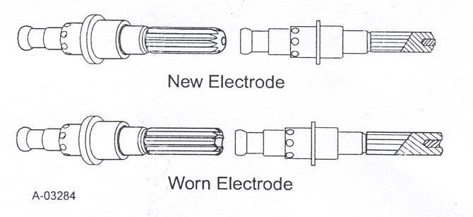
6934900010

                                                           funzionamento del generatore.
INSTALLAZIONE
ATTENZIONE:                                                ALLACCIAMENTO CIRCUITO PNEUMATICO:
Questa apparecchiatura in CLASSE A non e’                  Il THOR 123/123S usa aria compressa come gas per
destinata all’uso in ambienti residenziali dove la         il plasma. Può essere usata quindi qualsiasi bombola
potenza elettrica e’ fornita dal sistema pubblico di       di aria compressa oppure aria proveniente da un
alimentazione a bassa tensione. Ci possono                 compressore. L’aria dovrà essere libera da particelle
essere potenziali difficoltà a garantire la                inquinanti, come olio, acqua o altri agenti contaminanti.
compatibilità elettromagnetica di questi ambienti a        Un regolatore di pressione è previsto per avere la
causa di disturbi condotti e irradiati. Il generatore      corretta portata d’aria sulla torcia.
THOR 123 non rispetta i limiti della IEC 61000-3-          CIRCUITO ARIA: vedere figura
12. Se collegato alla rete BT industriale pubblica è
responsabilità dell'installatore o dell'utilizzatore
assicurarsi,      previa    consultazione    dell'Ente
distributore, se lo stesso è collegabile.
Il generatore THOR 123 S rispetta i limiti
della IEC 61000-3-12 e puo’ essere collegato alla
rete BT industriale pubblica e privata.
Il buon funzionamento del generatore è assicurato da
un’ adeguata installazione; è necessario quindi:
- Sistemare la macchina in modo che non sia
compromessa la circolazione d’ aria assicurata dal
ventilatore interno .
- Evitare che i ventilatori immettano nella macchina       LEGENDA:
depositi o polveri.                                        1– Filtro aria
- E’ bene evitare urti, sfregamenti, ed in maniera         2– Riduttore (regolatore pressione)
assoluta l’ esposizione a stillicidi, fonti di calore      3– Manometro
eccessive, o comunque situazioni anomale.                  4-- Pressostato
                                                           5– Elettrovalvola
TENSIONE DI RETE
Il generatore funziona con queste tensione di              Si dovrà applicare una pressione più alta di 5 bar (5-
alimentazione:                                             5,5 bar) e portata minima di 130l/min al filtro aria posto
THOR 123 400V +/- 15% e Fuse rating di 25A                 sul pannello posteriore del THOR 123. La pressione
                                                           non dovrà superare i 6 bar. Il regolatore di pressione 2
COLLEGAMENTO                                               è impostato dalla ditta costruttrice a 4,8 bar.
- Prima di effettuare connessioni elettriche tra il        Controllare la pressione premendo il pulsante di Test
generatore di corrente e l’ interruttore di linea,         aria posto sul pannello anteriore e verificare sul
accertarsi che quest’ ultimo sia aperto.                   manometro 4,8 bar. Se si verificasse la necessità di
- Il quadro di distribuzione deve essere conforme alle     regolare la pressione, riferirsi alla procedura di
normative vigenti nel paese di utilizzo.                   regolazione nella sezione RICERCA GUASTI.
-L’ impianto di rete deve essere di tipo industriale.
-Predisporre una apposita spina che preveda                Si dovrà avere cura dei tubi di collegamento
l’alloggiamento dei conduttori del cavo di                 pneumatico perché eventuali strozzature dei tubi o
alimentazione.                                             eccessive lunghezze possono creare inconvenienti
-Per i cavi più lunghi maggiorare opportunamente la        durante il processo di taglio.
sezione del conduttore.                                    Il pressostato inibisce il funzionamento del generatore
-A monte, l’apposita presa di rete dovrà avere un          per pressione dell’ aria inferiore a 3 bar in quanto è
adeguato interruttore munito di fusibili ritardati.        insufficiente a garantire il corretto funzionamento in
                                                           taglio.
MESSA A TERRA
- Per la protezione degli utenti il generatore dovrà
essere assolutamente collegato correttamente
all’impianto di terra (NORMATIVE INTERNAZIONALI
DI SICUREZZA).
- E’ indispensabile predisporre una buona messa a
terra tramite il conduttore giallo-verde del cavo di
alimentazione, onde evitare scariche dovute a contatti
accidentali con oggetti messi a terra. Lo chassis (che è
conduttivo) è connesso elettricamente con il
conduttore di terra; non collegare correttamente a terra
l’ apparecchiatura può provocare shock elettrici
pericolosi per l’utente, e un non corretto

                                                                                                                    5
6934900010

SOLLEVAMENTO                                       DESCRIZIONE PANNELLO
ATTENZIONE:
THOR 123 peso 50kg / 110lbs
                                                   FRONTALE
                                                   - THOR 123

Sollevamento manuale
Per sollevare manualmente il generatore servirsi
delle due apposite maniglie.

                                                   1       Led presenza aria
                                                   2       Led allarme protezione
                                                   3       Pulsante test aria
                                                   4       Led sovratemperatura
Sollevamento tramite gancio e cinghia              5       Led abilitazione taglio
Per il sollevamento con gancio e cinghia usare     6       Led macchina sotto tensione
esclusivamente i le maniglie come indicato nel     7       Display Corrente
disegno.                                           8       Pulsante RESET
Durante il sollevamento tenere il generatore in    9       Interruttore ON-OFF
posizione orizzontale.                             10      Encoder regolazione corrente

                                                   MESSA IN OPERA
                                                    L’operatore addetto durante l’utilizzo della
                                                   macchina deve obbligatoriamente porsi nel lato
                                                   anteriore della stessa onde evitare che i fumi
                                                   prodotti dal taglio vengano aspirati (Attraverso le
                                                   aperture di aerazione frontali e laterali) all’interno
                                                   della macchina dai ventilatori di raffreddamento.
AVVERTENZA
                                                   Fare riferimento per le istruzioni di seguito
POSIZIONAMENTO                                     riportate alla figura 1:
PRECARIO                                           - Con il potenziometro di regolazione della corrente
Se il generatore cade può causare infortuni.       di uscita (10), impostare un valore adeguato allo
Non mettere in funzione o spostare il generatore   spessore da tagliare ed in accordo con la portata
nel caso si trovi in posizione precaria.           della linea.
Non posizionare il generatore su piani inclinati   - Commutare l’interruttore posto nel pannello
superiori a 10°.                                   anteriore (9).
                                                   - si accenderà il Led verde (6) (macchina sotto
                                                   tensione).
                                                   - si accenderà il Led verde (1) ad indicare la
                                                   presenza di aria compressa nel circuito aria.
                                                   - Il Led rosso (2) è acceso;

                                                   ATTENZIONE premere il pulsante RESET(8)

                                                   -Il Led rosso si spegne (2)
                                                   -Il Led giallo (4) spento significa che la
                                                   temperatura di funzionamento del generatore è nei
                                                   valori normali.
                                                   -Con il pulsante TEST GAS (3) verificare che la
                                                   pressione dell’aria compressa sia impostata
                                                   correttamente.
                                                   - Collegare il cavo positivo (Cavo Massa)
                                                   saldamente al pezzo da tagliare. (N.B: non

                                                                                                       6
6934900010

attaccare la pinza alla parte di materiale che verrà     - La corrente è troppo alta.
staccata con il taglio).
- Il generatore è ora pronto per lavorare. Quando si     TAGLIO A CONTATTO
vuole iniziare, posizionare la torcia sul pezzo da       Questo tipo di taglio si usa per materiali di
tagliare e premere il pulsante posto sulla torcia        spessore 5mm o inferiori.
stessa.                                                  - Togliere il distanziale e il TIP da 60A. Predisporre
- Ora l’arco viene trasferito al pezzo da tagliare.      la torcia montando i consumabili per il taglio a
Muovere la torcia secondo la direzione desiderata        contatto: Tip 40A e Deflector .
con una velocità che assicuri una buona qualità di       - Regolare la corrente dal minimo fino a 40A
taglio.                                                  (max).
- Quando il taglio è terminato, rilasciare il pulsante
torcia per spegnere l’arco; si avrà uscita dell’aria     Procedere con il traglio restando a contatto con il
per 15” per poter raffreddare le parti della torcia.     pezzo da tagliare.

CONSIGLI DI TAGLIO:
- Non innescare l’arco pilota in aria se non c’è la                               Deflector cod 6074400000
necessità. Questo provoca una sensibile riduzione                                 Tip 40A cod 6073800000
della durata dell’ugello.
- Partire con il taglio dal bordo del pezzo da
tagliare finché non si riesce a perforarlo.              MESSA FUORI SERVIZIO
- Verificare che durante il taglio i lapilli escano      L’operatore addetto dopo aver eseguito il taglio
dalla parte inferiore del pezzo. Se escono dalla         può mettere fuori servizio (spegnere) la macchina
parte superiore vuol dire che si sta muovendo la         rispettando le seguenti fasi (fare riferimento alla
torcia troppo velocemente o che non si ha la             figura 1):
potenza necessaria per forare il pezzo.                  1-Spegnere la macchina portando l’interruttore
- Tenere la torcia in posizione verticale ed                 di linea (9) in posizione “0“.
osservare l’arco lungo la linea di taglio.               2-Controllare che i Led macchina sotto tensione
Trascinando leggermente la torcia sul pezzo, si              (6) e presenza aria (1) siano spenti.
può mantenere un taglio regolare.                        3-Togliere la spina di connessione della
- Quando si tagliano materiali sottili, ridurre la       macchina alla presa di alimentazione elettrica.
potenza fino ad avere la migliore qualità di taglio.     4- Scollegare il cavo dal connettore positivo (Pinza
                                                         di Massa)
CONSIGLI PER LA PERFORAZIONE:
- Tenere la torcia circa ad 1 mm. di distanza dal        PULIZIA INTERNA DELLA MACCHINA
pezzo da tagliare prima di premere il pulsante           Prima di eseguire la pulizia interna della macchina
torcia. Si allunga così la vita dell’ugello.             è obbligatorio rispettare le avvertenze sopra
- Iniziare il taglio con un piccolo angolo piuttosto     descritte e procedere secondo le seguenti fasi:
che con una posizione verticale della torcia.            1- Togliere la capotta svitando le apposite viti
Questo permette al metallo fuso di uscire da un          laterali;
lato piuttosto che schizzare indietro verso l’ugello,    2- Togliere ogni traccia di polvere dalle parti
proteggendo così l’operatore dai lapilli ed              interne della macchina mediante getto d’aria
aumentando la vita dell’ugello stesso.                   compressa con pressione non superiore a 3 bar;
- Impugnare la torcia rivolta lontano dal proprio        3- Controllare visivamente tutte le connessioni
corpo e lentamente portarla in posizione verticale.      elettriche, assicurandosi che viti e dadi siano ben
(Importante quando si tagliano spessori sottili).        serrati;
Assicurarsi che la torcia sia puntata lontano da Voi     4- Controllare visivamente lo stato di tutti i
e dalle persone attorno a Voi per evitare danni          componenti: sostituire eventuali componenti
provocati da lapilli di metallo fuso.                    deteriorati;
- Quando il foro è completato procedere col taglio.      5- Rimontare la capotta avvitando le apposite viti
                                                         laterali.
MALFUNZIONAMENTI COMUNI DURANTE IL
TAGLIO:                                                  MANUTENZIONE PREVENTIVA
Il pezzo non è completamente forato.                     Ispezionare saltuariamente (ogni 3-4 mesi)
Le cause possono essere:                                 l’interno del generatore, togliendo i depositi di
- La corrente è troppo bassa.                            polvere sugli organi interni affinché non venga
- La velocità di taglio è troppo alta.                   compromesso       il   loro   raffreddamento     e
- I componenti della torcia sono consumati.              funzionamento. La frequenza di tale operazione è
- Il pezzo da tagliare ha uno spessore troppo            in funzione della posizione della macchina e della
grosso. Presenza di materiali di scarto sul fondo        quantità    di   polvere    e   depositi   presenti
del taglio. Le cause possono essere:                     nell’atmosfera di lavoro. Controllare spesso che i
- La velocità di taglio è troppo bassa.                  cablaggi e le connessioni di potenza siano ben
- I componenti della torcia sono consumati.              fissati.

                                                                                                             7
6934900010

RICAMBIO PARTI CONSUMATE                                  torcia. NON toccare alcun componente interno
Attenzione! L’ugello della torcia e le parti              della torcia quando la spia di segnalazione
limitrofe raggiungono temperature elevate                 dell’alimentatore è accesa .
durante l’uso, per evitare pericolo di ustioni            Pulire l’interno della torcia con un detergente per
attendere il raffreddamento prima di effettuare           contatti elettrici utilizzando un batuffolo di ovatta o
operazioni di manutenzione.                               un panno umido morbido.

Saltuariamente, o in caso si notino delle anomalie        Nei casi più gravi, la torcia può essere scollegata
di funzionamento, ispezionare l’ugello della torcia       dai conduttori e pulita più accuratamente versando
per vedere se vi sono stati danneggiamenti. Se il         un detergente per contatti elettrici all’interno della
foro dell’ugello è deteriorato o di aspetto ovale, è      torcia e soffiando al suo interno aria compressa.
tempo di sostituire le parti di ricambio. Ispezionare
l’elettrodo: se il centro dell’elettrodo ha una cavità    ATTENZIONE
con una profondità maggiore di 1,5 mm sostituirlo.        Asciugare accuratamente        la   torcia   prima   di
Sostituire parti della torcia non richiede                rimontarla.
attrezzature particolari. parti della torcia non
richiede attrezzature particolari. Basta svitare il       MALFUNZIONAMENTI COMUNI
cappuccio di ritenuta e tutte le parti componenti la      Di seguito vengono elencati i malfunzionamenti più
torcia sono facilmente sostituibili. Quando si svita il   comuni in fase di taglio con le possibili cause.
cappuccio di ritenuta si sente un piccolo click
dovuto ad un microswitch che disabilita la                1. Penetrazione insufficiente
macchina per evitare partenze accidentali . Una           a. Velocità di taglio troppo alta
volta risistemata la torcia, per iniziare a lavorare si   b. Inclinazione eccessiva della torcia
deve premere il pulsante di RESET.                        c. Spessore eccessivo del metallo
                                                          d. Componenti della torcia usurati
                                                          e. Corrente di taglio troppo bassa
INTERVENTI                                                f. Componenti non originali della thermal dynamics
La presente sezione descrive le procedure
essenziali di manutenzione che possono essere             2. Spegnimento dell’arco principale
eseguite dall’operatore. Altre regolazioni o              a. Velocità di taglio troppo bassa
riparazioni dovranno essere effettuate unicamente         b. Eccessiva distanza tra torcia e pezzo lavorato
da personale opportunamente addestrato.                   c. Corrente di taglio troppo alta
                                                          d. Cavo di lavoro scollegato
AVVERTENZE                                                e. Componenti della torcia usurati
Scollegare l’alimentazione principale alla fonte          f. Componenti non originali della thermal dynamics
prima di smontare la torcia o i conduttori della
torcia.                                                   3. Formazione eccessiva di scorie
Rileggere spesso le precauzioni importanti in             a. Velocità di taglio troppo bassa
materia di sicurezza riportate all’inizio del presente    b. Eccessiva distanza tra torcia e pezzo lavorato
manuale. Accertarsi che l’operatore sia provvisto di      c. Componenti della torcia usurati
guanti, indumenti, occhiali e protezioni per le           d. Corrente di taglio inadeguata
orecchie adeguati. Sincerarsi che nessuna parte           e. Componenti non originali della thermal
del corpo dell’operatore entri in contatto con il         dynamics
pezzo lavorato quando la torcia viene azionata.
                                                          4. Breve durata dei componenti della torcia
ATTENZIONE                                                a. Olio o umidità nella fonte di aria
Le scintille provocate dal processo di taglio             b. Superamento della capacità del sistema
possono causare danni a superfici rivestite,              (materiale troppo spesso)
verniciate o altre come vetro, plastica e metallo.        c. Tempo eccessivo dell’arco pilota
MANUTENZIONE DELLA TORCIA                                 d. Flusso di aria troppo basso (pressione non
A. Pulizia della torcia                                   corretta)
Anche se si adottano precauzioni per utilizzare           e. Componenti non originali della thermal
soltanto aria pulita con la torcia, è possibile che       dynamics
all’interno della torcia si accumulino residui. Tali
accumuli possono influire sull’accensione dell’arco
pilota e sulla qualità complessiva del taglio
eseguito con la torcia.

AVVERTENZE
Scollegare l’alimentazione principale dal sistema
prima di smontare la torcia o i conduttori della

                                                                                                               8
6934900010
ISPEZIONE E SOSTITUZIONE DEI
COMPONENTI USURATI NELLA TORCIA
AVVERTENZE
Scollegare l’alimentazione principale dal sistema
prima di smontare la torcia o i conduttori della
torcia. NON toccare alcun componente interno
della torcia quando la spia di segnalazione 5. Estrarre l’elettrodo direttamente dal corpo torcia.
dell’alimentatore è accesa. Verificare che la faccia dell’elettrodo non presenti
Smontare i componenti soggetti a usura della un’usura eccessiva facendo riferimento alle figure
torcia come segue: di seguito.
NOTA 6. Rimontare l’elettrodo spingendolo direttamente
La shield cup trattiene in posizione la punta e la nel corpo torcia finché non scatta in posizione.
cartuccia di start. Posizionare la torcia con la
shield cup rivolta verso l’alto per evitare che i 7. Rimontare la cartuccia di start e la punta
componenti cadano quando si rimuove la shield desiderate nel corpo torcia.
cup.
8. Serrare manualmente la shield cup finché non è
1. Svitare e smontare la shield cup dalla torcia.
alloggiata nel corpo torcia. Se si percepisce una
certa resistenza nel momento in cui si monta la
NOTA
shield cup, prima di procedere verificare le
L’accumulo di scorie sulla shield cup che non si
lettature.
riesce a rimuovere può influire sulle prestazioni del
sistema.
2. Verificare che la shield cup non presenti danni.
Pulirla con un panno o sostituirla nel caso in cui sia
danneggiata.
GUIDA ALLA RISOLUZIONE DEI GUASTI
Questa sottosezione descrive come procedere alla
risoluzione dei guasti nel caso in cui occorra
smontare la torcia ed eseguire misurazioni
elettroniche. Tali procedure sono utili per risolvere
molti problemi comuni che possono manifestarsi
con questo tipo di torcia.
COME UTILIZZARE LA GUIDA
Le informazioni fornite di seguito intendono aiutare
Componenti soggetti a usura il cliente/l’operatore a stabilire le cause più
probabili di vari sintomi. La guida è strutturata
3. Smontare la Tip. Verificare che non presenti come segue:
un’usura eccessiva (segnalata da un orifizio
allungato o sovradimensionato). Pulire o sostituire X. Sintomo (in grassetto)
la tip ove del caso. Eventuali istruzioni particolari (in testo normale)
1. Causa (in corsivo)
a. Controllo/soluzione (in testo sottolineato)
Individuare il sintomo, consultare le cause (le
cause sono elencate partendo dalle più frequenti),
quindi le soluzioni. Effettuare le riparazioni del
caso ricordandosi di controllare che l’aggancio sia
4. Smontare la cartuccia di start. Verificare che perfettamente funzionante dopo gli eventuali
non presenti un’usura eccessiva, fori del gas interventi eseguiti.
ostruiti o scolorimenti. Accertarsi che il raccordo
all’estremità inferiore si muova liberamente.
Sostituirla ove del caso.
96934900010
Risoluzione dei guasti: a. Verificare che la shield cup sia perfettamente
alloggiata contro la testa della torcia (non stringere
A. La fiamma pilota della torcia non si accende eccessivamente).
quando si attiva l’interruttore della torcia
1. Led rosso reset sempre acceso 3. Protezione sicurezza torcia o malfunzionamento
a. Verificare che la shield cup sia montata in dell’ interruttore della torcia
maniera corretta. a. Verificare che la shield cup sia montata
correttamente.
2. O-ring superiore sulla testa della torcia in b. Controllare la continuità dell’interruttore
posizione non corretta nell’impugnatura della torcia manuale o nel corpo
a. Smontare la shield cup dalla torcia; verificare la della torcia se installata su una macchina.
posizione dell’O-ring superiore. Correggerla ove
del caso. 4. Componenti malfunzionanti nel gruppo torcia e
cavo torcia
3.Interruttore della torcia o sicurezza torcia a. Ispezionare i gruppi della torcia e sostituirli ove
malfunzionante del caso.
a. Verificare la continuità dell’interruttore della
torcia e della sicurezza torcia. 5. Componenti malfunzionanti nel generatore
a. Restituire per la riparazione o richiedere un
intervento di assistenza da parte di un tecnico
qualificato conformemente al Manuale di
assistenza.
C. Potenza limitata senza alcun controllo
1. Collegamenti di entrata o uscita all’generatore
inadeguati
a. Verificare tutti i collegamenti di entrata e uscita.
2. Componenti malfunzionanti nel gruppo torcia e
cavo torcia
a. Ispezionare i componenti della torcia e sostituirli
ove del caso.
4. Componenti della torcia malfunzionanti 3. Componenti malfunzionanti nel generatore
a. Ispezionare i componenti della torcia e sostituirli a. Restituire per la riparazione o richiedere un
ove del caso. Consultare la Sezione 10.9, intervento di assistenza da parte di un tecnico
Ispezione e sostituzione dei componenti soggetti a qualificato conformemente al Manuale di
usura della torcia. assistenza.
5. Pressione del gas troppo bassa D. Taglio irregolare o non corretto
a. Impostare la pressione operativa del gas 1. Collegamenti di entrata o uscita al generatore
corretta. inadeguati
a. Verificare tutti i collegamenti di entrata e uscita.
6. Componenti malfunzionanti nel gruppo torcia e
conduttori 2. Corrente impostata troppo bassa sul generatore
a. Ispezionare i gruppi della torcia e sostituirli ove a. Aumentare l’impostazione della corrente.
del caso.
3. Torcia spostata troppo rapidamente sul pezzo
7. Componenti malfunzionanti nell’impianto lavorato
a. Restituire per la riparazione o richiedere un a. Ridurre la velocità di taglio
intervento di assistenza da parte di un tecnico
qualificato conformemente al Manuale di 4.Olio o umidità eccessiva nella torcia
assistenza. a. Tenere la torcia a 3,2 mm da una superficie
pulita durante lo spurgo e osservare se è presente
B. La torcia non taglia una formazione di olio o umidità (non azionare la
1. Torcia non collegata correttamente torcia).
all’alimentatore
a. Verificare che il cavo torcia sia correttamente E. Assenza del flusso di gas
collegato all’alimentatore. 1. Gas non collegato o pressione troppo bassa
a. Verificare la fonte per accertarsi che la
2. Shield cup non montata correttamente. sulla pressione operativa del gas sia corretta
torcia 2. Componenti malfunzionanti nella torcia e
106934900010
conduttori ALLARME PULSANTE
a. Ispezionare i componenti della torcia e sostituirli
ove necessario. Il led (2) è acceso e lampeggia velocemente e il
display visualizza "TRI".
3. Componenti malfunzionanti nell’alimentatore
a. Restituire per la riparazione o richiedere un
intervento di assistenza da parte di un tecnico
qualificato conformemente al Manuale di
assistenza.
F. Taglio eseguito, ma inadeguato
1. Corrente impostata troppo bassa sul generatore
a. Aumentare l’impostazione della corrente.
2. Torcia spostata troppo rapidamente sul pezzo
lavorato
a. Ridurre la velocità di taglio
3. Olio o umidità eccessiva nella torcia 1. L’operatore accende il generatore con il
a. Tenere la torcia a 3,2 mm da una superficie pulsante torcia premuto.
pulita durante lo spurgo e osservare se è presente
una formazione di olio o umidità (non azionare la 2. Il generatore è bloccato.
torcia). 3. Spegnere il generatore e controllare la torcia.
Vedere la sezione SERVICE.
DIFETTI PIP (PART IN PLACE)
Il led (2) è acceso , lampeggia lentamente e il
In questa sezione vengono descritti I più comuni display visualizza "PIP".
malfunzionamenti e come vengono indicati
MANCANZA ARIA
Il led (1) di presenza aria si spegnerà.
1. I consumabili non sono montati correttamente.
2. Il generatore è bloccato.
1. No aria nel sistema 3. Spegnere il generatore e controllare I
consumabili .
2. Controllare il flusso d’aria
Vedere la sezione SERVICE.
Controllare che il tubo dell’aria sia correttamente
collegato al regolatore ,posto sul retro del
generatore , e che la pressione sia corretta.
(vedi INSTALLAZIONE - CIRCUITO
PNEUMATICO )
116934900010
RESET DUTY CYCLE E
Il led (2) è acceso senza lampeggiare e il display
visualizza l’amperaggio.
SOVRATEMPERATURA
Il led 3 è acceso e il display visualizza HT (1,3,5,7)
Il ciclo di intermittenza è la percentuale di utilizzo
della saldatrice su 10 minuti che l’ operatore deve
rispettare per evitare che scatti il blocco di
erogazione per sovratemperatura.
1. Il generatore è semplicemente in STAND-BY. Se la macchina entra in sovratemperatura:
2. Premere il pulsante RESET (7). - Il led giallo si accende in modo
intermittente .
Vedere la sezione STATING UP - E’ necessario attendere circa 10 minuti per
riprendere a saldare.
SMALTIMENTO
APPARECCHIATURE
ELETTRICHE ED
ELETTRONICHE
Non smaltire le apparecchiature
elettriche assieme ai rifiuti normali!
In ottemperanza alla Direttiva
Europea 2002/96/CE sui rifiuti da
apparecchiature elettriche ed
elettroniche e relativa attuazione
nell'ambito della legislazione
nazionale, le apparecchiature elettriche giunte a
fine vita devono essere raccolte separatamente e
conferite ad un impianto di riciclo ecocompatibile.
In qualità di proprietario delle apparecchiature
dovrà informarsi presso il nostro rappresentante in
loco sui sistemi
IN CASO DI CATTIVO FUNZIONAMENTO
RICHIEDETE L’ASSISTENZA DI PERSONALE
QUALIFICATO.
126934900010
must be free from damage to the insulation. BARE
SAFETY CABLES ARE DANGEROUS. Do not use the
ELECTRIC SHOCK CAN KILL machine if the power cable is damaged; it must be
- Disconnect the power supply before working on replaced immediately.
the welding machine. - if it is necessary to open the machine, first
- Do not work with deteriorated cable sheaths. disconnect the power supply. Wait 5 minutes to
- Do not touch bare electrical parts. allow the capacitors to discharge. Failure to take
- Ensure that all the panels covering the welding this precaution may expose the operator to
machine are firmly secured in place when the dangerous risks of electric shock.
machine is connected to the mains supply. - never work with the welding machine if the
- Insulate yourself from the work bench and from protective cover is not in place.
the floor (ground): use insulating footwear and - ensure that the earth connection of the power
gloves. supply cable is perfectly efficient.
- Keep gloves, footwear, clothes, the work area This machine has been designed for use in a
and this equipment clean and dry. professional and industrial environment. For other
types of application contact the manufacturer. If
PRESSURISED CONTAINERS CAN EXPLODE electromagnetic disturbances are found it is the
IF WELDED. responsibility of the machine user to solve the
When working with a welding machine: problem with the technical assistance of the
- do not weld pressurised containers . manufacturer.
- do not weld in environments containing explosive It is forbidden for people with PACEMAKERS to
powders or vapours. use or come near the machine.
THE RADIATIONS GENERATED BY THE
WELDING ARC CAN DAMAGE THE EYES AND
CAUSE BURNING OF THE SKIN.
WARNING
- Provide suitable protection for the eyes and body.
- It is indispensable for contact lens wearers to
protect themselves with suitable lenses and
masks.
NOISE CAN DAMAGE YOUR HEARING.
- Protect yourself suitably to avoid hearing
damage.
FUMES AND GASES CAN DAMAGE YOUR
HEALTH.
- Keep your head out of the reach of fumes.
- Provide suitable ventilation of the work area.
- If the ventilation is not sufficient, use an exhaust
system that sucks from the bottom.
HEAT, SPLASHES OF MOLTEN METAL AND
SPARKS CAN CAUSE FIRES.
- Do not weld near inflammable materials.
- Avoid having any type of fuel with you such as
cigarette lighters or matches. PREVENTION OF BURNS
- The welding arc can cause burns. Keep the tip of To protect your eyes and skin from burns and
the electrode far from your body and from other ultraviolet rays:
persons. - wear dark glasses. Wear suitable clothing, gloves
and footwear.
PREVENTION OF ELECTRIC SHOCKS - use masks with closed sides, having lenses and
Take the following precautions when working with protective glass according to standards (degree of
a welding machine: protection DIN 10).
- keep yourself and your clothes clean. - warn people in the vicinity not to look directly at
- do not be in contact with damp or wet parts when the arc.
working with the welding machine.
- maintain suitable insulation against electric PREVENTION OF FIRE
shock. If the operator has to work in a damp Welding produces splashes of molten metal.
environment, he must take extreme care and wear Take the following precautions to prevent fire:
insulating footwear and gloves. - ensure that there is a fire extinguisher in the
- check the machine power cable frequently: it welding area.
136934900010
- remove all inflammable material from the
immediate vicinity of the welding area.
COMPLAINTS
- cool the welded material or let it cool before Complaints for damage during transport: If your
touching it or putting it in contact with combustible equipment is damaged during transit you must
material present a claim to the carrier.
- never use the machine for welding containers of Complaints for faulty goods: All the equipment
potentially inflammable material. These containers shipped by STEL is subjected to strict quality
must be completely cleaned before they are control. However, if your equipment does not work
welded. properly, consult your authorise dealer.
- ventilate the potentially inflammable area before
using the machine. TECHNICAL DATA
- do not use the machine in atmospheres
containing high concentrations of powders,
inflammable gases or combustible vapours.
A
GENERAL
CHARACTERISTICS
The Inverter power source supplies adjustable
continuous current to provide maximum cutting
performance. B
The Inverter has been designed with the latest
advanced technology available, providing the
following advantages:
- Low weight to allow maximum ease of handling.
- The inverter technology allows a stable arc to be
C
obtained, which ensures high cutting quality for a
D
great variety of metals and thicknesses.
- The pilot arc can perforate painted or rusty
metals. a) IDENTIFICATION
- The continuous pilot arc allows easy cutting of Name, address of the manufacturer
perforated materials; the pilot arc is transferred to Type of Plasma machine
the piece that is to be cut when the torch is about 3 Identification with reference to serial number
mm. away from the cutting surface. Symbol of the type of Plasma machine
- The regulating potentiometer, positioned on the Reference to the construction standards
front panel, sets the cutting current of the machine.
- The Inverter operates with compressed air . b) WELDING OUTPUT
The air used must be free from impurities, oil or Symbol of the work process
other polluting substances. Symbol for Plasma machines suitable for working in
an environment with a high risk of electric shock.
DELIVERY OF THE MATERIAL Symbol of the cutting current
Assigned no-load voltage (mean voltage)
The package contains:
Range of the welding current
- N. 1 Inverter
Values of the intermittent cycle (in 10 minutes)
- N. 1 instructions manual
Values of the assigned cutting current
- N. 1 torch
Values of the conventional loaded voltage
- N. 1 earth cable
- N. 1 air connection
c) POWER SUPPLY
Power supply symbol (number of phases and
Check that all the material listed above is included
frequency)
in the package. Inform your distributor if anything is
Assigned power supply voltage
missing.
Maximum power supply current
Check that the Inverter has not been damaged in
Maximum effective power supply current (identifies
transport. If you see any sign of damage, consult
the line fuse)
the COMPLAINTS section for instructions.
Before working with a THOR Plasma Inverter, read
d) OTHER CHARACTERISTICS
the SAFETY and USE section of this manual.
Degree of protection .
146934900010
PNEUMATIC CIRCUIT CONNECTION:
INSTALLATION The THOR uses compressed air for plasma
WARNING: This Class A equipment is not cutting. Any cylinder of compressed air may
intended for use in residential locations where the therefore be used, or air from a compressor. The
electrical power is provided by the public low- air must be free from polluting particles, such as oil
voltage supply system. There may be potential or other contaminating agents. A pressure
difficulties in ensuring electromagnetic regulator is provided to ensure the correct air flow
compatibility in those locations, due to conducted rate on the torch.
as well as radiated disturbances.
This equipment does not comply with IEC 61000-
3-12. If it is connected to a public low voltage
system, it is the responsibility of the installer or
user of the equipment to ensure, by consultation
with the distribution network operator if necessary,
that the equipment may be connected. The good
operation of the machine is ensured by correct
installation; you must therefore proceed as follows:
- Position the machine in such a way that there is
no obstacle to the air circulation ensured by the
internal fan since the internal components require
suitable cooling. KEY:
- Ensure that the fan does not send deposits or 1– Air filter
dust into the machine. 2– Reducer (pressure regulator)
- Avoid impacts, rubbing, and absolutely no 3– Pressure gauge
exposure to dripping water, excessive heat 4– Pressure switch
sources, or any abnormal situations. 5– Solenoid valves
MAINS VOLTAGE A pressure higher than 5 bar (5-5.5 bar) must be
The Inverter operates from a mains voltage supply: applied to the air filter located on the rear panel of
THOR 123 400V +/- 15% and Fuse rating di 25A the THOR (100l/min). The pressure must not
exceed 6 bar. The pressure regulator 1 is set by
CONNECTION the manufacturer at 4.8 bar. Check the pressure by
- Before making the electrical connections between pressing the Air Test button on the front panel and
the Inverter and the line switch, ensure that the check that the pressure gauge gives a reading of
switch is turned off . 4.8 bar. If it should be necessary to regulate the
- The distribution panel must comply with the pressure, refer to the regulating procedure in the
regulations in force in the country of use. TROUBLE SHOOTING section.
- The mains system must be of the industrial type.
- When using long extension cables, the core Pay particular attention to the pneumatic
diameter section is increased as required for connection cables. Any blockage of the tubes or
optimum performance. excessive lengths may cause problems during the
- The power input supply socket must have a suitable cutting process.
switch provided with #slow burning' type fuse(s).
- In the event of damage to the power cable, A pressure switch set at 3 bar inhibits operation
replacement or repair must be performed by a when the pressure at output of the reducer is
qualified person at an approved service centre. insufficient to guarantee operation.
EARTHING
- To ensure user protection the Inverter must by
law be correctly connected to the earth system
(INTERNATIONAL SAFETY REGULATIONS).
- It is indispensable to provide good earthing by
means of the yellow-green wire in the power cable,
in order to avoid discharges due to accidental
contacts with earthed objects .
- The chassis (which is conductive) is electrically
connected with the earth wire; if the equipment is
not suitably connected to earth it may cause
electric shocks which are dangerous to the user
and those nearby.
156934900010
LIFTING FRONT PANEL DESCRIPTION
WARNING:
THOR 123 peso 50kg / 110lbs
- THOR 123
Lifting by hand:
Lift the machine using the two handles provided.
1 Air presence led
2 Protection alarm led
Lifting with hoist and strap 3 Air test button
Lift the machine by using ONLY both handles as 4 Excess temperature led
shown on the picture. 5 Enable cutting led
Keep the machine as horizontal as possible 6 Machine live led
7 Current display
8 RESET button
9 ON-OFF switch
10 Cutting current regulation
STARTING UP
INSTRUCTION FOR The operator may start up the machine only after
having read and understood all parts of this
INSECURE POSITIONING manual. Depending on the type of cut to be
Failure to properly secure the machine can cause performed he must follow the work phases
personal injury. described below.
If machine is in an insecure position do not attempt 1- Ensure that the work environment and your
to switch on. clothing satisfy the safety requirements described.
Do not put the machine on an unlevelled surface 2- Position the Inverter in a place where there is no
greater than 10°. obstruction to air circulation.
3- Connect the THOR to a suitable power socket
(an earthed socket is obligatory).
4- Connect the compressed air pipe to the air filter
on the rear panel.
5- Ensure that there is no water in the filter. If
necessary, empty the filter.
For the instructions below, refer to the details :
- With the potentiometer for regulating the output
current (10), set a suitable value for the thickness
that is to be cut, in agreement with the line
capacity.
- Turn the switch on the front panel (9).
- the green led (6) will light up (machine live).
- the green led (1) will light up to indicate the
presence of compressed air in the air circuit.
- The red Led (2) is illuminated.
ATTENTION press the RESET button (8)
- The red Led (2) switches off
- When the yellow Led (4) is off it means that the
THOR working temperature is within normal
166934900010
values. − Incorrect torch angle
- With the TEST GAS button (3) check that the - The piece to be cut is too thick.
pressure of the compressed air has been correctly Presence of waste material on the bottom of the
set. cut.
- Connect the positive cable (Earth Clamp) firmly to The causes may be:
the piece to be cut. (N.B.: do not attach the clamp − The cutting speed is too low
to the part of material that will be cut off). − Insufficient cutting current
- The Inverter is now ready for work. When you − Incorrect torch angle
want to start, position the torch on the work-piece − The cutting current is too high
to be cut and press the button on the torch. − Torch components are worn.
- Now the arc is transferred to the work-piece to be − Travel speed is too slow
cut. Move the torch in the desired direction at a
speed that ensures a good cutting quality.
-When the cut is finished, release the torch button CONTACT CUTTING
to stop the arc; air will continue to flow out for 15 This type of cut is used for materials with thickness
seconds to cool the torch parts. 5mm or less.
- Remove the spacer and the 60A TIP. Prepare the
CUTTING: torch, fitting the consumable parts for contact
-Do not freely or unnecessarily ignite the pilot arc cutting: Tip 40A and Deflector.
when not cutting! This action considerably - Regulate the current from minimum up to 40A
reduces the life of the nozzle. (max).
-Start cutting from the edge of the work- piece, until - Make the cut, remaining in contact with the work-
you manage a perforation. piece to be cut.
-Ensure that, during cutting, the sparks fall away
from the bottom of the work-piece. If sparks or
dross come out at the top it means that the torch is Deflector cod 6074400000
being moved too fast or that there is not the Tip 40A cod 6073800000
necessary power to perforate the work-piece.
-Keep the torch in a vertical position and observe
the arc along the cutting line. By dragging the torch
lightly on the work-piece you can keep the cut SWITCHING OFF
regular. After having made the cut, the operator may switch
-When cutting thin materials, reduce the power to off the machine as follows :
give optimum cutting quality. 1- Switch off the machine turning the line switch
(9) to position “0“.
PIERCING: 2- Check that the machine live Led (6) and the air
- Hold the torch at a distance of approximately 1 presence Led (1) are off.
mm. from the work-piece before pressing the torch 3- Disconnect the plug of the machine from the
button. This distance will prolong the life of the power socket.
nozzle and other parts. 4- Disconnect the cable from the connector (earth
- Start cutting at a slight angle rather than with the clamp).
torch in a vertical position. This allows the molten
material to come out at one side instead of spitting CLEANING THE INSIDE OF THE MACHINE:
back towards the nozzle, thus protecting the ALWAYS DISCONNECT INPUT PRIMARY
operator against sparks and increasing the life of SUPPLY!!!
the nozzle. Before cleaning the inside of the machine it is
- Hold the torch facing away from your body and obligatory to FIRST follow the WARNINGS
bring it slowly into the vertical position. (This is described above and to proceed as follows:
important when cutting thick gauges). Ensure that 1- Remove the casing, slackening the side screws;
the torch is pointed away from you and from 2- Remove all traces of dust from the internal parts
anyone else in the vicinity, to avoid damage of the machine by means of a jet of compressed
caused by sparks of molten metal. air at a pressure no higher than 3 Kg/cm2;
- When the pierced hole has been completed, 3- Visually check all the electrical connections,
carry on with cutting. ensuring that the screws and nuts are well
secured;
COMMON MALFUNCTIONS DURING CUTTING: 4- Visually check the state of all the components:
The work-piece is not completely perforated. replace any deteriorated components;
The causes may be: 5- Put back the casing, tightening the side screws.
− The current is too low.
− The cutting speed is too fast.
− The torch components are worn.
176934900010
PREVENTIVE MAINTENANCE OF POWER body comes into contact with the work-piece while
SOURCE. the torch is active.
ALWAYS DISCONNECT INPUT PRIMARY
SUPPLY!!! CAUTION
Inspect the inside of the POWER SOURCE Sparks from the cutting process can cause
INVERTER from time to time (every 3-4 weeks damage to coated, painted, and other surfaces
depending on usage and environment), removing such as glass, plastic and metal.
the deposits of dust from the inside parts so that
GENERAL TORCH MAINTENANCE
their cooling and operation is not impeded. The
- A. Cleaning Torch
frequency of this operation depends on the
Even when precautions are taken to use only clean
position of the machine and on the quantity of dust
air with a torch, eventually the inside of the torch
and deposits in the working atmosphere.
becomes coated with residue. This build-up can
Frequently check that the power cables and
affect the pilot arc initiation and the overall cut
connections are securely fastened.
quality of the torch.
CHANGING WORN PARTS
WARNING.
Attention! The torch nozzle and the
ALWAYS DISCONNECT INPUT PRIMARY
neighbouring parts reach high temperatures
SUPPLY!!!
during use; to avoid the risk of burns, wait for
Disconnect primary power to the system before
them to cool down before carrying out
disassembling the torch or torch leads.
maintenance work!
DO NOT touch any internal torch parts while the
AC indicator light of the power supply is ON.
From time to time, or if you notice any
The inside of the torch should be cleaned with
malfunctions, inspect the torch nozzle to see
electrical contact cleaner using a cotton swab or
whether there is any damage. If the nozzle hole is
soft wet rag. In severe cases, the torch can be
deteriorated or appears to be oval, it is time to
removed from the leads and cleaned more
change the spare parts.
thoroughly by pouring electrical contact cleaner
Inspect the electrode: if the centre of the electrode
into the torch and blowing it through with
has a cavity deeper than 1.5 mm, change it.
compressed air.
No particular tools are needed to change the torch
parts. Just unscrew the closing cap and all the
CAUTION
torch components can be easily replaced. When
Dry the torch thoroughly before reinstalling.
you unscrew the cap you hear a slight click due to
a micro switch which disables the machine so as to COMMON OPERATING FAULTS
avoid accidental starts. Once the torch is in order, The following lists the more common cutting faults
to start work again you must press the RESET and possible causes:
button.
1. Insufficient penetration
SPECIAL MAINTENANCE
a. Cutting speed too fast
For any special maintenance jobs, it is essential to b. Torch not at 90°
have the necessary technical knowledge and c. Metal too thick
suitable equipment. Otherwise apply to the nearest d. Worn torch parts
assistance centre. e. Cutting current too low
f. NON- genuine manufacturer parts
SERVICE
This section describes basic maintenance 2. Cutting Arc Extinguishes
procedures performable by operating personnel. a. Cutting speeds too slow
No other adjustments or repairs are to be b. Torch stand-off too high from work piece
attempted by other than properly trained c. Cutting current too high
personnel. d. Work cable disconnected
e. Worn torch parts
f. NON- genuine manufacturer parts
WARNING:
ALWAYS DISCONNECT INPUT PRIMARY 3. Excessive dross Formation
SUPPLY!!! a. Cutting speeds too slow
Disconnect primary power at the source before b. Torch stand-off too high from work piece
disassembling of torch leads. c. Worn torch parts
Frequently review the important safety precautions d. Improper cutting current
at the front of this Manual. Be sure the operator is e. NON- genuine manufacturer parts
equipped with proper gloves, clothing, eye and ear
protection. Make sure no part of the operator’s
186934900010
4. Short Life of Torch parts excessive wear plugged gas holes, or
a. Oil or moisture in air source discolouration. Check the lower end fittings for free
b. Exceeding system capability (material too thick) motion. Replace if necessary.
c. Excessive pilot arc time
d. Air flow too low (incorrect air pressure)
e. Improperly assembled torch
f. NON- genuine manufacturer parts
INSPECTION AND REPLACEMENT
CONSUMABLE TORCH PARTS
WARNING: 5. Pull the electrode straight out of the torch head.
ALWAYS DISCONNECT INPUT PRIMARY Check the face of the electrode for excessive
SUPPLY!!! wear. Refer to the following figure.
Disconnect primary power to the system before 6. Re-install the electrode by pushing it straight
disassembling the torch or torch leads into the torch head until it clicks.
DO NOT touch any internal torch parts while the 7. Re-install the desired starter cartridge and tip
AC indicator light of the power supply is ON. into the torch head
Remove the consumable torch parts as follows 8. Hand tighten the shield cup until it is seated on
the torch head. If resistance is felt when installing
the cup, check the threads before proceeding.
NOTE
The shield cup holds the tip and the starter
cartridge shield cup in place. Position the torch
with the shield cup facing out when the cup is
removed.
1. Unscrew and remove the shield cup from the
torch
GUIDE FOR THE FAULTS and SOLUTIONS
NOTE This subsection covers troubleshooting that
Slag build-up on the shield cup that cannot be requires disassembly and electronic
removed may effect the performance of the measurements. It is helpful for solving many of the
system. common problems that can arise with this torch
2. Inspect the cup for damage. Wipe it clean or assembly.
replace if damaged
- HOW TO USE THIS GUIDE
The following information is a guide to help the
customer / operator determine the most likely
causes for various symptoms.
This guide is set up as follows:
X. symptom (bold type)
Any special instruction (text type)
1. Cause (italic type))
a. Check/remedy (text type/underlined)
Locate your symptom, check the causes (easiest
listed first) then remedies. Repair as needed being
sure to verify that unit is fully operational after any
Consumables parts repairs.
- Troubleshooting
3. Removed the tip. Check for excessive wear
(indicated by an elongated or oversize - A. torch will not pilot when switch is
orifice).Clean or replace the tip if necessary. activated
1.red led always on.
a. Check that shield cup is properly installed.
2.Upper O-ring on torch head is in wrong position.
a. Remove shield cup from torch; check position of
upper O-ring. Correct if necessary.
4. Remove the starter cartridge. Check for 3.Upper o-ring on torch head is in wrong position.
196934900010
a. Remove shield cup from torch; check position of a. Inspect torch assemblies and replace if
upper o-ring. Correct if necessary. necessary.
3.faulty components in power supply
a. return for repair or have qualified technician
repair as per service manual
D. erratic or improper cutting output
1. poor input or output connections to power
supply
a. check all input and output connections
2. current set too low at power supply
4. faulty torch switch or torch security a. increase current setting
a. Check torch or security torch switch for
continuity. 3.torch is being moved too fast across work piece
a. reduce cutting speed
5.faulty torch parts
a. inspect torch parts and replace if necessary. 4.excessive oil or moisture in torch
Refer to section 5.04.inspection and replacement a. hold 1/8 inch (3.2 mm) from clean surface while
consumable torch parts. purging and observe oil or moisture
6 gas pressure too low E. No Gas Flow
a. set proper operating gas pressure. 1. gas not connected or pressure too low
a. check source proper operating gas pressure
7. Faulty components in torch and leads assembly
a. Inspect torch assemblies and replace if 2.faulty components in torch and wiring assembly
necessary a. inspect torch assemblies and replace if
necessary
8. Faulty components in power supply
a. Return for repair or have qualified technician 3.faulty components in power supply
repair as per service manual. a. return for repair or have qualified technician
repair as per service manual
B. No cutting output F. torch cuts but not adequately
1. torch not properly connect to the system 1.current set too low at power supply
a. Check that torch wires are properly attached to a. increase current setting.
system
2. torch is being moved too fast across work piece
2. shield cup not properly installed on torch a. reduce cutting speed
a. Check that shield cup is fully seated against
torch head ( do not over tighten) 3. excessive oil or moisture in torch
a. hold 1/8 inch (3.2 mm) from clean surface while
3. Security thermal protection or faulty torch switch purging observe oil or moisture build-up (do note
a. Check that shield cup is properly installed activate torch)
b. Check switch – in hand torch handle or in
machine torch head for continuity.
4. faulty components in torch assemblies and
replace if necessary
a. inspect torch assemblies and replace if
necessary
5. faulty components in the system
a. return for repair or have qualified technician
repair as per service manual
C. limited output with no control
1. poor input or output connection to power supply
a. check all input and output connections.
2.Faulty components in torch and wiring assembly
20Puoi anche leggere