SISTEMA DI STRUTTURE COMPONIBILI PER IMPIANTI FOTOVOLTAICI - METAL FRAMINGS SYSTEM FOR PHOTOVOLTAIC INSTALLATIONS
←
→
Trascrizione del contenuto della pagina
Se il tuo browser non visualizza correttamente la pagina, ti preghiamo di leggere il contenuto della pagina quaggiù
SISTEMA DI STRUTTURE COMPONIBILI
         PER IMPIANTI FOTOVOLTAICI
          METAL FRAMINGS SYSTEM
     FOR PHOTOVOLTAIC INSTALLATIONS

www.sati.it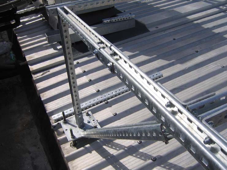
SISTEMA DI STRUTTURE
COMPONIBILI PER IMPIANTI
FOTOVOLTAICI
METAL FRAMINGS SYSTEM FOR
PHOTOVOLTAIC INSTALLATIONS

Profilati di ancoraggio ............................................................. pag. 11
Channels
Piastre di raccordo .................................................................. pag. 12
Fittings
Viterie ........................................................................................ pag. 25
Screws
SISTEMA DI STRUTTURE COMPONIBILI PER IMPIANTI FOTOVOLTAICI
METAL FRAMINGS SYSTEM FOR PHOTOVOLTAIC INSTALLATIONS
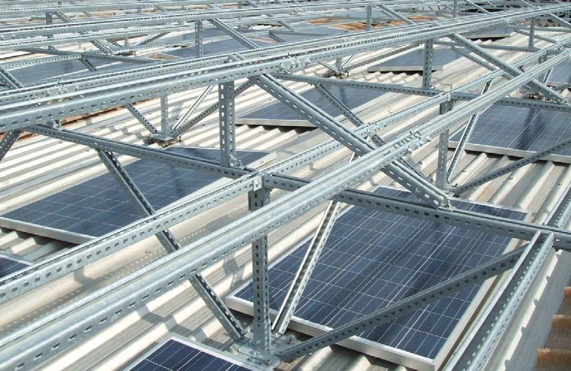
ESEMPIO DI MONTAGGIO / ASSEMBLY EXAMPLE
Esempio di struttura su cui appoggeranno i pannelli fotovoltaici
Example of the structure of which will support the photovoltaic panels
Esempio di ancoraggio su lamiere grecate / Example anchor of corrugated sheets
4 Tutte le misure sono in mm. • All measurements are in mm.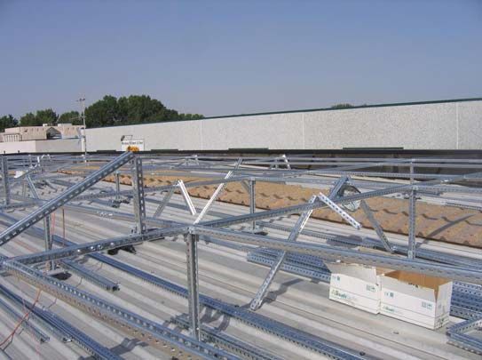
SISTEMA DI STRUTTURE COMPONIBILI PER IMPIANTI FOTOVOLTAICI
METAL FRAMINGS SYSTEM FOR PHOTOVOLTAIC INSTALLATIONS
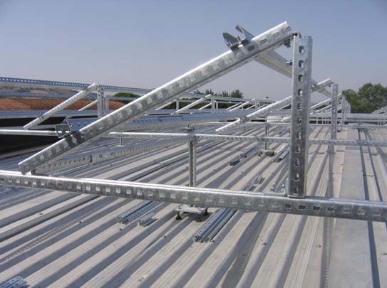
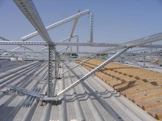
ESEMPIO DI MONTAGGIO / ASSEMBLY EXAMPLE
Struttura in fase di montaggio / Structure during assembly
Struttura in fase di montaggio / Structure during assembly
Tutte le misure sono in mm. • All measurements are in mm. 5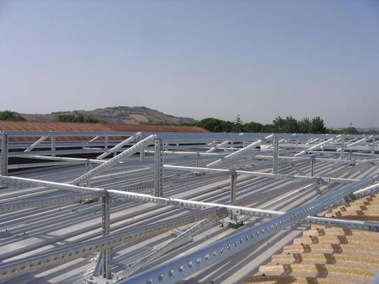
SISTEMA DI STRUTTURE COMPONIBILI PER IMPIANTI FOTOVOLTAICI
    METAL FRAMINGS SYSTEM FOR PHOTOVOLTAIC INSTALLATIONS

    ISTRUZIONI TECNICHE / TECHNICAL INSTRUCTIONS
    Sistema modulare pratico, veloce ed economico per comporre ogni               Practical,fast and economic modular system used to make up any type
    tipo di struttura portante, robusta, regolabile. Profilati, piastre di        of load-bearing, robust and adjustable structure. Channels,fittings and
    raccordo e ancoraggio, attacchi speciali e altri accessori possono            special attachments can be used in any situation; in addition, a hacksaw
    essere utilizzati in qualunque situazione; inoltre un seghetto e una          and a wrench are the only instruments needed to assemble any type of
    chiave inglese sono i soli strumenti necessari per il montaggio di            basic structure.
    qualsiasi struttura di base.                                                  The system is compatible with the fittings of hot-deep and Sendzimir
    Il sistema è compatibile con gli accessori dei sistemi di sospensione in      galvanized steel systems for SATI S2 - S5 - S3 cable runways, and it is
    acciaio zincato a caldo e Sendzimir per le canalizzazioni SATI S2 - S5        particularly appropriate for laying cable trays-trunkings-ductings, fluid
    - S3, ed è particolarmente indicato per la posa di passerelle e canali        or gas pipes, air ducts, etc. in civil, service and industrial system
    portacavi, cavidotti, tubazioni per fluidi o gas, condotte d’aria ecc.,       engineering.
    nell’impiantistica civile, terziaria e industriale.
                                                                                  Materials
    Materiali                                                                     ■   PRP channels: made in Fe 360 hot-deep galvanized carbon steel
    ■   Profilati PRP: sono in acciaio al carbonio Fe 360 zincato a caldo             (according to DIN 50976 standards) and using reinforcement
        dopo lavorazione (secondo norme DIN 50976), e realizzati con                  profiling; length 3 m; thickness 2.5 mm; slots 11 x 20 mm, with 50
        profilatura di rinforzo; lunghezza 3 m; spessore 2,5 mm; asole 11 x           mm center to center.
        17 mm, con interasse 35 mm.                                               ■   PRL - PRM channels: made in Fe 360 Sendzimir galvanized steel
    ■   Profilati PRL - PRM: sono in acciaio Fe 360 zincato Sendzimir, e              Fe 360 and using reinforcement profiling; with or without slots;
        realizzati con profilatura di rinforzo; sono di tipo con asole e senza        lenght 3 m; thickness 2 mm; slots 11 x 20 mm, with 50 mm center
        asole; lunghezza 3 m; spessore 2 mm; asole 11 x 20 mm, con                    to center.
        interasse 50 mm.                                                          ■   PR fitting: made in Fe 360 hot-deep galvanized carbon steel
    ■   Piastre di raccordo PR: sono in acciaio al carbonio Fe 360 zincato            (according to EN ISO 1461 standards); width 40 mm; thickness 6
        a caldo dopo lavorazione (secondo norme EN ISO 1461); larghezza               mm; holes Ø 13.5 mm; interaxis between holes 50 mm; distance
        40 mm; spessore 6 mm; fori Ø 13,5 mm; interasse tra i fori 50 mm;             from centre to end plate hole 20 mm.
        distanza da centro foro a fine piastra 20 mm.                             ■   Bolts and screws:
    ■   Viterie:                                                                      - PAP (for PRP channel) and PMP (for PRM channel), spring nuts
        - Piastrine PAP (per profilati PRP) e PMP (per profilati PRM), con               with disposable contrast spring in electrolytic galvanized steel:
            molla di contrasto “a perdere”, in acciaio zincato                           M10 thread (M12 on request) also suitable for hot-deep
            elettroliticamente; filettatura M10 (a richiesta M12) adatta anche           galvanized steel, provided that we supply them.
            per viti zincate a caldo, purchè da noi fornite.                          - VTA anchor head screws (for PRL and PRM channels) in
        - Viti testa ad ancora, VTA (per profilati PRL e PRM) zincate                    electroplated zinc steel; thread M10 x 30.
            elettroliticamente; filettatura M10 x 30.                                 - BZF hot-deep galvanized screws, and washers (according to
        - Viti e rondelle BZF zincate a caldo (secondo norme CEI 7.6),                   CEI standard 7.6), BZE electrolytic galvanized, M10 thread (M12
            BZE zincate elettroliticamente; filettatura M10 (a richiesta M12).           on request).

    Criteri costruttivi                                                           Construction criterias
    ■   Per la costruzione di strutture portanti si assemblano i profilati PRP    ■   For the construction of load-bearing structures, assembly PRP -
        - PRL - PRM tramite le piastre di raccordo PR, utilizzando le                 PRL - PRM channels using PR fittings, PAP - PMP spring nuts,
        piastrine PAP - PMP, le viti testa ad ancora VTA, le viti e le rondelle       VTA anchor head screws and BZF - BZE M10 x 30 screws. Spring
        BZF - BZE M10 x 30. Le piastrine, le viti e le rondelle devono                nuts, screws and washers and screws must be ordered separately.
        essere ordinate a parte.                                                  ■   The slots in the PRP - PRL - PRM channels, increases the number
    ■   La presenza di asole nei profilati PRP - PRL - PRM, accresce il               of possible compositions. In addition to PR fittings, enables all the
        numero di composizioni possibili. Si possono utilizzare oltre alle            fittings of the hot-deep galvanized support system to be used, such
        piastre di raccordo PR, anche tutti gli accessori del sistema di              as MP brackets, SSP - SDP - SRP - SCP - DPP supports, as well
        sospensione zincato a caldo quali le mensole MP, e i supporti SSP             as those for galvanized Sendzimir system, in particular ML - PSM
        - SDP - SRP - SCP - DPP, oltre a quelli del sistema zincato                   - SSM.
        Sendzimir, in particolare ML - PSM - SSM.

    Come montare
    Making connections

    1                                   2                                   3                                               4

6                                                                                                              Tutte le misure sono in mm. • All measurements are in mm.
SISTEMA DI STRUTTURE COMPONIBILI PER IMPIANTI FOTOVOLTAICI
   METAL FRAMINGS SYSTEM FOR PHOTOVOLTAIC INSTALLATIONS

   ISTRUZIONI TECNICHE / TECHNICAL INSTRUCTIONS

                                                                                                                  Caratteristiche / Characteristics
                                                                                                                   Area / Area             03,0824      cm2
                                                                                                           Peso lineare / Linear weight    02,4196      kg/m
                                                                                                           Peso lineare / Linear weight    02,3736     daN/m
                                                                                                                        Jx                 07,9599      cm4
                                                                                                                         Wx                03,8825      cm3
                                                                                                                         ρx                01,6069      cm2
                                                                                                                         Jy                11,8420      cm4
                                                                                                                         Wy                04,7368      cm3
                                                                                                                         ρy                01,9601      cm2

   Tab. 1 Profilato di ancoraggio PRP - asolato / Channel PRP - slotted                                                       Cod. 2520452

       Luce               Carico max. concentrato            Freccia      Carico max. uniformemente            Freccia             Carico max. di punta
                                in mezzeria                                       distribuito

       Span                Max. load concentrated           Deflection   Max. load distributed uniformly      Deflection
                                in the middle                                                                                      Max. column loading
         L                   P                P                 fP            Q                 Q                 fQ                F               F
       mm                    N                kg               mm             N                 kg               mm                 N              kg
       0250                 9156             933              00,18         18312              1867             00,23             49910           5088
       0500                 4578             467              00,73         09156              0933             00,91             49910           5088
       0750                 3052             311              01,64         06104              0622             02,04             49910           5088
       1000                 2289             233              02,91         04578              0467             03,64             49910           5088
       1250                 1831             187              04,54         03662              0373             05,68             49910           5088
       1500                 1526             156              06,54         03052              0311             08,18             46755           4766
       1750                 1308             133              08,91         02616              0267             11,13             34351           3502
       2000                 1145             117              11,63         02289              0233             14,54             26300           2681
       2250                 1017             104              14,72         02035              0207             18,40             20780           2118
       2500                 0916             093              18,18         01831              0187             22,72             16832           1716
       2750                 0832             085              21,99         01665              0170             27,49             13911           1418
       3000                 0763             078              26,17         01526              0156             32,72             11689           1192
       3500                 0654             067              35,62         01308              0133             44,53             08588           0875
       4000                 0572             058              46,52         01145              0117             58,16             06575           0670

   PORTATE DEL PROFILATO                                                          LOADS OF THE CHANNEL
   Le portate ammissibili sono relative alle seguenti condizioni di impiego:      The permitted loads are referred to the following working conditions:
   - trave appoggiata alle estremità su semplici appoggi;                         - simple beam laid on two supports;
   - perfetto ritorno elastico;                                                   - deflection complete elastic return;
   - sollecitazione ammissibile: 140 N/mm2;                                       - permitted working stress: 140 N/mm2;
   - coefficiente di sicurezza: ≥ 2,5.                                            - safety factor: ≥ 2,5.
   I carichi riportati in tabella sono:                                           The loads pointed out in the table are:
   - carico “P”; concentrato in mezzeria;                                         - concentrated load in the middle “P”;
   - carico “Q” uniformemente distribuito;                                        - uniformly distributed load “Q”;
   - carico “F” di punta.                                                         - maximum column loading “F”.
   Per condizioni di impiego diverse (disposizione del carico e appoggi) i        In any other working conditions (load disposition and supports), load
   valori di carico e di freccia si ottengono moltiplicando “Q” e “fQ” per i      and deflection are obtained getting the product of “Q” and “fQ”
   fattori corrispondenti riportati nella tabella di conversione (Tab. 6).        respectively with the corrispondant factor in the conversion table (Tab. 6).

   CARICO DI PUNTA                                                                COLUMN LOAD
   Il carico di punta “F” indicato in tabella è riferito ad un carico assiale     Column load “F” is pointed out in the table and it is referred to an axial
   baricentrico.                                                                  barycentric load.

   CONDIZIONI FAVOREVOLI DI LAVORO                                                FAVOURABLE CONDITIONS FOR WORK
   Qualora le condizioni di installazione consentano di accettare un              When the working conditions permit a safety factor 2 (permitted working
   coefficiente di sicurezza pari a 2 (sollecitazione ammissibile 175 N/mm2)      stress 175 N/mm2) the loads P, Q and the deflections f listed in the table
   i carichi P, Q e le frecce f riportati in tabella possono essere aumentati     can be increased by 30%.
   del 30%.

Tutte le misure sono in mm. • All measurements are in mm.                                                                                                        7
SISTEMA DI STRUTTURE COMPONIBILI PER IMPIANTI FOTOVOLTAICI
    METAL FRAMINGS SYSTEM FOR PHOTOVOLTAIC INSTALLATIONS

    ISTRUZIONI TECNICHE / TECHNICAL INSTRUCTIONS

                                                                                                                 Caratteristiche / Characteristics
                                                                                                                   Area / Area                  2,1724         cm2
                                                                                                          Peso lineare / Linear weight          1,7050        kg/m
                                                                                                          Peso lineare / Linear weight          1,6726       daN/m
                                                                                                                       Jx                       5,6403         cm4
                                                                                                                        Wx                      2,6744         cm3
                                                                                                                         ρx                     1,9910         cm2
                                                                                                                         Jy                     6,1601         cm4
                                                                                                                        Wy                      3,0049         cm3
                                                                                                                         ρy                     2,1089         cm2

    Tab. 2 Profilato di ancoraggio PRM - asolato / Channel PRM - slotted                                                      Cod. 2020202

       Luce            Carico max. concentrato            Freccia         Carico max. uniformemente           Freccia                Carico max. di punta
                             in mezzeria                                          distribuito

       Span             Max. load concentrated           Deflection     Max. load distributed uniformly      Deflection
                             in the middle                                                                                           Max. column loading
         L                P                P                 fP               Q                Q                 fQ                   F               F
        mm                N                kg               mm                N                kg               mm                    N              kg
       0250              5991             611              00,17            11981             1221             00,21                41707           4251
       0500              2995             305              00,67            05991             0611             00,84                41707           4251
       0750              1997             204              01,51            03994             0407             01,89                41707           4251
       1000              1498             153              02,69            02995             0305             03,36                41707           4251
       1250              1198             122              04,20            02396             0244             05,24                41707           4251
       1500              0998             102              06,04            01997             0204             07,55                33130           3377
       1750              0856             087              08,22            01712             0174             10,28                24340           2481
       2000              0749             076              10,74            01498             0153             13,43                18636           1900
       2250              0666             068              13,59            01331             0136             16,99                14724           1501
       2500              0599             061              16,78            01198             0122             20,98                11927           1216
       2750             0545              056              20,31            01089             0111             25,38                09857           1005
       3000             0499              051              24,17            00998             0102             30,21                08283           0844
       3500             0428              044              32,89            00856             0087             41,12                06085           0620
       4000             0374              038              42,96            00749             0076             53,70                04659           0475

    PORTATE DEL PROFILATO                                                        LOADS OF THE CHANNEL
    Le portate ammissibili sono relative alle seguenti condizioni di impiego:    The permitted loads are referred to the following working conditions:
    - trave appoggiata alle estremità su semplici appoggi;                       - simple beam laid on two supports;
    - perfetto ritorno elastico;                                                 - deflection complete elastic return;
    - sollecitazione ammissibile: 140 N/mm2;                                     - permitted working stress: 140 N/mm2;
    - coefficiente di sicurezza: ≥ 2,5.                                          - safety factor: ≥ 2,5.
    I carichi riportati in tabella sono:                                         The loads pointed out in the table are:
    - carico “P”; concentrato in mezzeria;                                       - concentrated load in the middle “P”;
    - carico “Q” uniformemente distribuito;                                      - uniformly distributed load “Q”;
    - carico “F” di punta.                                                       - maximum column loading “F”.
    Per condizioni di impiego diverse (disposizione del carico e appoggi) i      In any other working conditions (load disposition and supports), load
    valori di carico e di freccia si ottengono moltiplicando “Q” e “fQ” per i    and deflection are obtained getting the product of “Q” and “fQ”
    fattori corrispondenti riportati nella tabella di conversione (Tab. 6).      respectively with the corrispondant factor in the conversion table (Tab. 6).

    CARICO DI PUNTA                                                              COLUMN LOAD
    Il carico di punta “F” indicato in tabella è riferito ad un carico assiale   Column load “F” is pointed out in the table and it is referred to an axial
    baricentrico.                                                                barycentric load.

    CONDIZIONI FAVOREVOLI DI LAVORO                                              FAVOURABLE CONDITIONS FOR WORK
    Qualora le condizioni di installazione consentano di accettare un            When the working conditions permit a safety factor 2 (permitted working
    coefficiente di sicurezza pari a 2 (sollecitazione ammissibile 175 N/mm2)    stress 175 N/mm2) the loads P, Q and the deflections f listed in the table
    i carichi P, Q e le frecce f riportati in tabella possono essere aumentati   can be increased by 30%.
    del 30%.

8                                                                                                              Tutte le misure sono in mm. • All measurements are in mm.
SISTEMA DI STRUTTURE COMPONIBILI PER IMPIANTI FOTOVOLTAICI
METAL FRAMINGS SYSTEM FOR PHOTOVOLTAIC INSTALLATIONS
ISTRUZIONI TECNICHE / TECHNICAL INSTRUCTIONS
Caratteristiche / Characteristics
Area / Area 1,81240 cm2
Peso lineare / Linear weight 1,42270 kg/m
Peso lineare / Linear weight 1,39570 daN/m
Jx 1,05270 cm4
Wx 0,94980 cm3
ρx 0,76213 cm2
Jy 4,79000 cm4
Wy 2,33660 cm3
ρy 1,62570 cm2
Tab. 4 Profilato di ancoraggio PRL - asolato / Channel PRL - slotted Cod. 2020152
Luce Carico max. concentrato Freccia Carico max. uniformemente Freccia Carico max. di punta
in mezzeria distribuito
Span Max. load concentrated Deflection Max. load distributed uniformly Deflection
in the middle Max. column loading
L P P fP Q Q fQ F F
mm N kg mm N kg mm N kg
0250 2128 217 00,32 4255 434 000,40 29060 2962
0500 1064 108 01,28 2128 217 001,60 29060 2962
0750 0709 072 02,87 1418 145 003,59 24734 2521
1000 0532 054 05,11 1064 108 006,39 13913 1418
1250 0426 043 07,98 0851 087 009,98 08904 0908
1500 0355 036 11,50 0709 072 014,37 06183 0630
1750 0304 031 15,65 0608 062 019,56 04543 0463
2000 0266 027 20,44 0532 054 025,55 03478 0355
2250 0236 024 25,87 0473 048 032,34 02748 0280
2500 0213 022 31,94 0426 043 039,92 02226 0227
2750 0193 020 38,64 0387 039 048,30 01840 0188
3000 0177 018 45,99 0355 036 057,49 01546 0158
3500 0152 015 62,60 0304 031 078,25 01136 0116
4000 0133 014 81,76 0266 027 102,20 00870 0089
PORTATE DEL PROFILATO LOADS OF THE CHANNEL
Le portate ammissibili sono relative alle seguenti condizioni di impiego: The permitted loads are referred to the following working conditions:
- trave appoggiata alle estremità su semplici appoggi; - simple beam laid on two supports;
- perfetto ritorno elastico; - deflection complete elastic return;
- sollecitazione ammissibile: 140 N/mm2; - permitted working stress: 140 N/mm2;
- coefficiente di sicurezza: ≥ 2,5. - safety factor: ≥ 2,5.
I carichi riportati in tabella sono: The loads pointed out in the table are:
- carico “P”; concentrato in mezzeria; - concentrated load in the middle “P”;
- carico “Q” uniformemente distribuito; - uniformly distributed load “Q”;
- carico “F” di punta. - maximum column loading “F”.
Per condizioni di impiego diverse (disposizione del carico e appoggi) i In any other working conditions (load disposition and supports), load
valori di carico e di freccia si ottengono moltiplicando “Q” e “fQ” per i and deflection are obtained getting the product of “Q” and “fQ”
fattori corrispondenti riportati nella tabella di conversione (Tab. 6). respectively with the corrispondant factor in the conversion table (Tab. 6).
CARICO DI PUNTA COLUMN LOAD
Il carico di punta “F” indicato in tabella è riferito ad un carico assiale Column load “F” is pointed out in the table and it is referred to an axial
baricentrico. barycentric load.
CONDIZIONI FAVOREVOLI DI LAVORO FAVOURABLE CONDITIONS FOR WORK
Qualora le condizioni di installazione consentano di accettare un When the working conditions permit a safety factor 2 (permitted working
coefficiente di sicurezza pari a 2 (sollecitazione ammissibile 175 N/mm2) stress 175 N/mm2) the loads P, Q and the deflections f listed in the table
i carichi P, Q e le frecce f riportati in tabella possono essere aumentati can be increased by 30%.
del 30%.
Tutte le misure sono in mm. • All measurements are in mm. 9SISTEMA DI STRUTTURE COMPONIBILI PER IMPIANTI FOTOVOLTAICI
METAL FRAMINGS SYSTEM FOR PHOTOVOLTAIC INSTALLATIONS
COEFFICIENTI DI CONVERSIONE PER TRAVI CON DIVERSE CONDIZIONI DI CARICO STATICO
CONVERSION FACTOR FOR BEAMS WITH VARIOUS STATIC LOADING CONDICTIONS
Tabella 6
CONDIZIONI DI PORTATA E APPOGGIO SCHEMA COEFFICIENTE COEFFICIENTE
DI PORTATA DI FRECCIA
LOAD AND SUPPORT CONDITION FIGURE LOAD FACTOR DEFLECTION
FACTOR
Trave semplicemente appoggiata
Carico uniformemente distribuito
1,00 1,00
Simple beam laid on two supports
Uniform load
Trave semplicemente appoggiata
Due carichi uguali concentrati a 1/4 di L
1,00 1,10
Simple beam laid on two supports
Two equal concentrated loads at 1/4 of L
Trave incastrata da due lati
Carico uniformemente distribuito
1,50 0,30
Beam fixed at both ends
Uniform load
Trave incastrata da due lati
Carico concentrato in mezzeria
1,00 0,40
Beam fixed at both ends
Concentrated load at center
Trave incastrata ad una estremità
Carico uniformemente distribuito
0,25 2,40
Cantilever beam
Uniform load
Trave incastrata ad un estremità
Carico concentrato in punta
0,12 3,20
Cantilever beam
Concentrated load at end
Trave continua, due campate uguali
Carico uniformemente distribuito su una campata
1,30 0,92
Continuous beam, two equal spans
Uniform load on one span
Trave continua, campate uguali
Carico uniformemente distribuito
1,00 0,42
Continuous beam, equal spans
Uniform load
Trave continua, due campate uguali
Carico concentrato al centro di una campata
0,62 0,71
Continuous beam, two equal spans
Concentrated load at center of one span
Trave continua, campate uguali
Carico concentrato al centro delle campate
0,67 0,48
Continuous beam, equal spans
Concentrated load at center of spans
10 Tutte le misure sono in mm. • All measurements are in mm.SISTEMA DI STRUTTURE COMPONIBILI PER IMPIANTI FOTOVOLTAICI
METAL FRAMINGS SYSTEM FOR PHOTOVOLTAIC INSTALLATIONS
PROFILATI DI ANCORAGGIO / CHANNELS
Profilato di ancoraggio - PRP Codice kg/m Conf.m
Code kg/m Pack.m
Channel - PRP ZF
2520452 2,650 3
Profilato di ancoraggio - PRL Codice Codice kg/m Conf.m
Code Code kg/m Pack.m
Channel - PRL ZS ZF
2020152 2520152 1,370 3
Profilato di ancoraggio - PRM Codice Codice kg/m Conf.m
Code Code kg/m Pack.m
Channel - PRM ZS ZF
2020202 2520202 1,920 3
Tutte le misure sono in mm. • All measurements are in mm. 11SISTEMA DI STRUTTURE COMPONIBILI PER IMPIANTI FOTOVOLTAICI
METAL FRAMINGS SYSTEM FOR PHOTOVOLTAIC INSTALLATIONS
PIASTRE DI RACCORDO / FITTINGS
Piastra - PR 101 Esempio di montaggio / Assembly example Codice kg/pz Conf.pz
Code kg/pcs Pack.pcs
Fitting - PR 101 ZF
2610001 0,085 1
Piastra - PR 102 Esempio di montaggio / Assembly example Codice kg/pz Conf.pz
Code kg/pcs Pack.pcs
Fitting - PR 102 ZF
2610002 0,170 1
Piastra - PR 103 Esempio di montaggio / Assembly example Codice kg/pz Conf.pz
Code kg/pcs Pack.pcs
Fitting - PR 103 ZF
2610003 0,260 1
Piastra - PR 104 Esempio di montaggio / Assembly example Codice kg/pz Conf.pz
Code kg/pcs Pack.pcs
Fitting - PR 104 ZF
2610004 0,350 1
12 Tutte le misure sono in mm. • All measurements are in mm.SISTEMA DI STRUTTURE COMPONIBILI PER IMPIANTI FOTOVOLTAICI
METAL FRAMINGS SYSTEM FOR PHOTOVOLTAIC INSTALLATIONS
PIASTRE DI RACCORDO / FITTINGS
Piastra - PR 105 Esempio di montaggio / Assembly example Codice kg/pz Conf.pz
Code kg/pcs Pack.pcs
Fitting - PR 105 ZF
2610005 0,430 1
Piastra - PR 106 Esempio di montaggio / Assembly example Codice kg/pz Conf.pz
Code kg/pcs Pack.pcs
Fitting - PR 106 ZF
2610006 0,400 1
Piastra - PR 107 Esempio di montaggio / Assembly example Codice kg/pz Conf.pz
Code kg/pcs Pack.pcs
Fitting - PR 107 ZF
2610007 0,250 1
Piastra - PR 108 Esempio di montaggio / Assembly example Codice kg/pz Conf.pz
Code kg/pcs Pack.pcs
Fitting - PR 108 ZF
2610008 0,330 1
Tutte le misure sono in mm. • All measurements are in mm. 13SISTEMA DI STRUTTURE COMPONIBILI PER IMPIANTI FOTOVOLTAICI
METAL FRAMINGS SYSTEM FOR PHOTOVOLTAIC INSTALLATIONS
PIASTRE DI RACCORDO / FITTINGS
Piastra - PR 109 Esempio di montaggio / Assembly example Codice kg/pz Conf.pz
Code kg/pcs Pack.pcs
Fitting - PR 109 ZF
2610009 0,330 1
Piastra - PR 110 Esempio di montaggio / Assembly example Codice kg/pz Conf.pz
Code kg/pcs Pack.pcs
Fitting - PR 110 ZF
2610010 0,410 1
Piastra - PR 124 Esempio di montaggio / Assembly example Codice kg/pz Conf.pz
Code kg/pcs Pack.pcs
Fitting - PR 124 ZF
2610024 0,330 1
Piastra - PR 111 Esempio di montaggio / Assembly example Codice kg/pz Conf.pz
Code kg/pcs Pack.pcs
Fitting - PR 111 ZF
2610011 0,160 1
14 Tutte le misure sono in mm. • All measurements are in mm.SISTEMA DI STRUTTURE COMPONIBILI PER IMPIANTI FOTOVOLTAICI
METAL FRAMINGS SYSTEM FOR PHOTOVOLTAIC INSTALLATIONS
PIASTRE DI RACCORDO / FITTINGS
Piastra - PR 112 Esempio di montaggio / Assembly example Codice kg/pz Conf.pz
Code kg/pcs Pack.pcs
Fitting - PR 112 ZF
2610012 0,250 1
Piastra - PR 113 Esempio di montaggio / Assembly example Codice kg/pz Conf.pz
Code kg/pcs Pack.pcs
Fitting - PR 113 ZF
2610013 0,250 1
Piastra - PR 114 Esempio di montaggio / Assembly example Codice kg/pz Conf.pz
Code kg/pcs Pack.pcs
Fitting - PR 114 ZF
2610014 0,330 1
Piastra - PR 125 Esempio di montaggio / Assembly example Codice kg/pz Conf.pz
Code kg/pcs Pack.pcs
Fitting - PR 125 ZF
2610025 0,250 1
Tutte le misure sono in mm. • All measurements are in mm. 15SISTEMA DI STRUTTURE COMPONIBILI PER IMPIANTI FOTOVOLTAICI
METAL FRAMINGS SYSTEM FOR PHOTOVOLTAIC INSTALLATIONS
PIASTRE DI RACCORDO / FITTINGS
Piastra - PR 126 Esempio di montaggio / Assembly example Codice kg/pz Conf.pz
Code kg/pcs Pack.pcs
Fitting - PR 126 ZF
2610026 0,250 1
Piastra - PR 127 Esempio di montaggio / Assembly example Codice kg/pz Conf.pz
Code kg/pcs Pack.pcs
Fitting - PR 127 ZF
2610027 0,350 1
Piastra - PR 128 Esempio di montaggio / Assembly example Codice kg/pz Conf.pz
Code kg/pcs Pack.pcs
Fitting - PR 128 ZF
2610028 0,350 1
Piastra - PR 129 Esempio di montaggio / Assembly example Codice kg/pz Conf.pz
Code kg/pcs Pack.pcs
Fitting - PR 129 ZF
2610029 0,350 1
16 Tutte le misure sono in mm. • All measurements are in mm.SISTEMA DI STRUTTURE COMPONIBILI PER IMPIANTI FOTOVOLTAICI
METAL FRAMINGS SYSTEM FOR PHOTOVOLTAIC INSTALLATIONS
PIASTRE DI RACCORDO / FITTINGS
Piastra - PR 115 Esempio di montaggio / Assembly example Codice kg/pz Conf.pz
Code kg/pcs Pack.pcs
Fitting - PR 115 ZF
2610015 0,420 1
Piastra - PR 116 Esempio di montaggio / Assembly example Codice kg/pz Conf.pz
Code kg/pcs Pack.pcs
Fitting - PR 116 ZF
2610016 0,420 1
Piastra - PR 132 Esempio di montaggio / Assembly example Codice kg/pz Conf.pz
Code kg/pcs Pack.pcs
Fitting - PR 132 ZF
2610032 0,660 1
Piastra - PR 133 Esempio di montaggio / Assembly example Codice kg/pz Conf.pz
Code kg/pcs Pack.pcs
Fitting - PR 133 ZF
2610033 0,440 1
Tutte le misure sono in mm. • All measurements are in mm. 17SISTEMA DI STRUTTURE COMPONIBILI PER IMPIANTI FOTOVOLTAICI
METAL FRAMINGS SYSTEM FOR PHOTOVOLTAIC INSTALLATIONS
PIASTRE DI RACCORDO / FITTINGS
Piastra - PR 134 Esempio di montaggio / Assembly example Codice kg/pz Conf.pz
Code kg/pcs Pack.pcs
Fitting - PR 134 ZF
2610034 0,750 1
Piastra - PR 135 Esempio di montaggio / Assembly example Codice kg/pz Conf.pz
Code kg/pcs Pack.pcs
Fitting - PR 135 ZF
2610035 0,610 1
Piastra - PR 136 Esempio di montaggio / Assembly example Codice kg/pz Conf.pz
Code kg/pcs Pack.pcs
Fitting - PR 136 ZF
2610036 0,300 1
Piastra - PR 137 Esempio di montaggio / Assembly example Codice kg/pz α
Code kg/pcs α
Fitting - PR 137 ZF
2610037 0,250 45°
2610047 0,250 25°
2610048 0,250 30°
2610049 0,250 35°
18 Tutte le misure sono in mm. • All measurements are in mm.SISTEMA DI STRUTTURE COMPONIBILI PER IMPIANTI FOTOVOLTAICI
METAL FRAMINGS SYSTEM FOR PHOTOVOLTAIC INSTALLATIONS
PIASTRE DI RACCORDO / FITTINGS
Piastra - PR 138 Esempio di montaggio / Assembly example Codice kg/pz α
Code kg/pcs α
Fitting - PR 138 ZF
2610038 0,290 45°
2610051 0,290 65°
2610052 0,290 60°
2610053 0,290 55°
Piastra - PR 139 Esempio di montaggio / Assembly example Codice kg/pz Conf.pz
Code kg/pcs Pack.pcs
Fitting - PR 139 ZF
2610039 0,270 1
Piastra - PR 140 Esempio di montaggio / Assembly example Codice kg/pz Conf.pz
Code kg/pcs Pack.pcs
Fitting - PR 140 ZF
2610040 0,270 1
Piastra - PR 142 Esempio di montaggio / Assembly example Codice kg/pz Conf.pz
Code kg/pcs Pack.pcs
Fitting - PR 142 ZF
2610042 0,600 1
Tutte le misure sono in mm. • All measurements are in mm. 19SISTEMA DI STRUTTURE COMPONIBILI PER IMPIANTI FOTOVOLTAICI
METAL FRAMINGS SYSTEM FOR PHOTOVOLTAIC INSTALLATIONS
PIASTRE DI RACCORDO / FITTINGS
Piastra - PR 143 - PR 144 - PR 145 Codice Altezza Lungh. kg/pz Conf.pz
Code Height Length kg/pcs Pack.pcs
Fitting - PR 143 - PR 144 - PR 145 ZF
PR 143 2610043 200 200 0,600 1
PR 144 2610044 300 300 0,880 1
PR 145 2610045 400 400 1,470 1
Esempio di montaggio / Assembly example
Piastra - PR 117 Esempio di montaggio / Assembly example Codice kg/pz Conf.pz
Code kg/pcs Pack.pcs
Fitting - PR 117 ZF
2610017 0,560 1
Per profilato PRP.
For PRP profile.
Piastra - PR 118 Esempio di montaggio / Assembly example Codice kg/pz Conf.pz
Code kg/pcs Pack.pcs
Fitting - PR 118 ZF
2610018 0,450 1
Per profilato PRM.
For PRM profile.
20 Tutte le misure sono in mm. • All measurements are in mm.SISTEMA DI STRUTTURE COMPONIBILI PER IMPIANTI FOTOVOLTAICI
METAL FRAMINGS SYSTEM FOR PHOTOVOLTAIC INSTALLATIONS
PIASTRE DI RACCORDO / FITTINGS
Piastra - PR 119 Codice kg/pz Conf.pz
Code kg/pcs Pack.pcs
Fitting - PR 119 ZF
2610019 0,450 1
Piastra per fissaggio su travi con spessore max. 18 mm.
Fori Ø 11,5 mm.
Fornita completa di cavallotto zincato elettroliticamente,
rondelle, dadi M10.
Fitting for fixing on beams with max thickness 18 mm.
Holes Ø 11,5 mm.
Supplied complete of electrolityc galvanized “U” bolt,
washers, M10 nuts.
Esempio di montaggio / Assembly example
Piastra - PR 120 Codice kg/pz Conf.pz
Code kg/pcs Pack.pcs
Fitting - PR 120 ZF
2610020 0,240 1
Piastra per fissaggio su travi con spessore max. 18 mm.
Asole 13,5 x 17 mm.
Fornita completa di vite M10 x 50 zincata elettroliticamente,
dado, rondella.
* Ordinare a parte le piastrine
Fitting for fixing on beams with max thickness 18 mm.
Slots 13,5 x 17 mm.
Supplied complete of electrolitic galvanized screw M10 x
50, nut, washer.
* Spring nuts to be ordered separately.
Esempio di montaggio / Assembly example
Tutte le misure sono in mm. • All measurements are in mm. 21SISTEMA DI STRUTTURE COMPONIBILI PER IMPIANTI FOTOVOLTAICI
METAL FRAMINGS SYSTEM FOR PHOTOVOLTAIC INSTALLATIONS
PIASTRE DI RACCORDO / FITTINGS
Piastra - PR 121 Codice kg/pz Conf.pz
Code kg/pcs Pack.pcs
Fitting - PR 121 ZF
2610021 0,810 1
Per profilato PRP.
For PRP profile.
Esempio di montaggio / Assembly example
Piastra - PR 122 Codice kg/pz Conf.pz
Code kg/pcs Pack.pcs
Fitting - PR 122 ZF
2610022 0,600 1
Per profilato PRM.
For PRM profile.
Esempio di montaggio / Assembly example
22 Tutte le misure sono in mm. • All measurements are in mm.SISTEMA DI STRUTTURE COMPONIBILI PER IMPIANTI FOTOVOLTAICI
METAL FRAMINGS SYSTEM FOR PHOTOVOLTAIC INSTALLATIONS
PIASTRE DI RACCORDO / FITTINGS
Piastra - PR GPP Codice kg/pz Conf.pz
Code kg/pcs Pack.pcs
Fitting - PR GPP ZF
2520501 0,600 1
Per profilato PRP.
For PRP profile.
Esempio di montaggio / Assembly example
Piastra - GPRL - GPRM Tipo Codice Codice kg/pz Conf.pz
Type Code Code kg/pcs Pack.pcs
Fitting - GPRL - GPRM ZS ZF
GPRL 2020153 2520153 0,150 1
In acciaio zincato Sendzimir (ZS).
GPRM 2020203 2520203 0,200 1
In acciaio zincato a caldo per
immersione dopo lavorazione (ZF).
GPRL: per profilati PRL.
GPRM: per profilati PRM.
In Sendzimir galvanized steel (ZS).
In hot-dip galvanized steel after
machining (ZF).
GPRL: for PRL profiles.
GPRM: for PRM profiles.
GPRL GPRM
Esempio di montaggio / Assembly example
Tutte le misure sono in mm. • All measurements are in mm. 23SISTEMA DI STRUTTURE COMPONIBILI PER IMPIANTI FOTOVOLTAICI
METAL FRAMINGS SYSTEM FOR PHOTOVOLTAIC INSTALLATIONS
PIASTRE DI RACCORDO / FITTINGS
Staffa oscillante - STO Codice kg/pz Conf.pz
Code kg/pcs Pack.pcs
Beam clamp - STO
2610501 0,320 1
In acciaio tropicalizzato giallo.
A morsetto oscillante, per fissaggio su travi con spessore
max. 24 mm.
Completa di vite a punta indurita, staffa oscillante, dado
M10, rondella, dado speciale M10.
Adatta per aste filettate AS - M10.
In yellow galvanized steel.
Fitting with swinging clamp, to fix on beams with max.
thickness of 24 mm.
Complete of screw with hardened top, swinging rod, M10
nut, washer, special M10 nut.
Suitable to threaded rod AS - M10.
Esempio di montaggio / Assembly example
Piastra - PR 150 Codice kg/pz Conf.pz
Code kg/pcs Pack.pcs
Fitting - PR 150 ZF
2610050 4,000 1
Spessore 8 mm.
Thickness 8 mm.
Esempio di montaggio / Assembly example
24 Tutte le misure sono in mm. • All measurements are in mm.SISTEMA DI STRUTTURE COMPONIBILI PER IMPIANTI FOTOVOLTAICI
METAL FRAMINGS SYSTEM FOR PHOTOVOLTAIC INSTALLATIONS
VITERIE / SCREWS
Viti - Dadi - Rondelle - VDR
Screws - Nuts - Washers - VDR
BZF: In acciaio zincato a caldo (CEI 7.6 - UNI 3740).
BZE: In acciaio zincato elettroliticamente.
Per collegare i profilati PRP - PRL - PRM con le piastre PR.
Per altre viti, dadi, rondelle consultare le pagine dei “Sistemi di sospensione”.
BZF: In hot-dip galvanized steel (CEI 7.6 - UNI 3740).
BZE: In electroplated zinc steel.
To joint PRP - PRL - PRM channels to PR fittings.
For other screws, nuts, washers, see “Support system”.
A norme CEI EN 50085-1, 50085-2-1 / CEI EN Standard 50085-1, 50085-2-1
Barra filettata per sospensione - AS Lungh. Filettatura Codice kg/pz. Conf.pz
Length Thread Code kg/pcs Pack.pcs
Threaded rod - AS ZE
1000 M06 2020301 0,170 20
In acciaio zincato elettroliticamente (ZE).
M08 2020302 0,310 20
In galvanized steel (ZE). M10 2020303 0,400 20
M12 2020304 0,700 10
Manicotto di prolunga - MA Lungh. Filettatura Codice kg/pz. Conf.pz
Length Thread Code kg/pcs Pack.pcs
Rod coupling - MA ZE
50 M06 2020351 0,025 100
In acciaio zincato elettroliticamente (ZE).
M08 2020352 0,030 050
In galvanized steel (ZE). M10 2020353 0,040 025
M12 2020354 0,060 25
Vite Filettatura Codice Codice kg/conf. Conf.pz
Thread Code Code kg/pack. Pack.pcs
Screw BZE BZF
M08 x 20 2710151 – 1,300 100
Con quadro sottotesta.
M08 x 30 2710152 – 1,720 100
With short square section. M10 x 20 2710201 – 2,320 100
M10 x 30 2710202 – 2,800 100
Testa esagonale. M08 x 20 2710251 2720101 1,200 100
M08 x 30 2710252 2720102 1,500 100
Hex head cap. M10 x 20 2710301 2720151 2,300 100
M10 x 30 2710302 2720152 2,750 100
M10 x 50 2710303 – 2,950 100
Vite Filettatura Codice kg/conf. Conf.pz
Thread Code kg/pack. Pack.pcs
Screw BZE
M10 x 30 2710351 2,800 50
Testa ad ancora. Completa di dado e rondella.
Per fissaggi su profilati PRL - PRM - PRP.
Anchor head screws. Completa of nut and washer.
To fixing on PRL - PRM - PRP “U” sections.
Tutte le misure sono in mm. • All measurements are in mm. 25SISTEMA DI STRUTTURE COMPONIBILI PER IMPIANTI FOTOVOLTAICI
METAL FRAMINGS SYSTEM FOR PHOTOVOLTAIC INSTALLATIONS
VITERIE / SCREWS
Piastrina ad ancora - PAP Filettatura Codice Codice kg/conf. Conf.pz
Thread Code Code kg/pack. Pack.pcs
Spring nut - PAP BZE DACROMET
M08 2710601 2710611 1,500 50
In acciaio zincato elettroliticamente, con
M10 2710602 2710612 1,600 50
molla di contrasto “a perdere”.
Idonea per il solo profilato PRP.
La filettatura del dado si adatta anche alle viti
zincate a caldo BZF, purché da noi fornite.
In galvanized steel with spring.
Suitable for PRP “U” section only.
Nut thread is also suitable for BZF hot-dipped
screws, if provided by us.
Piastrina ad ancora - PMP Filettatura Codice kg/conf. Conf.pz
Thread Code kg/pack. Pack.pcs
Spring nut - PMP BZE
M10 2710652 1,600 50
In acciaio zincato elettroliticamente, con
molla di contrasto “a perdere”.
Idonea per il solo profilato PRM.
La filettatura del dado si adatta anche alle viti
zincate a caldo BZF, purché da noi fornite.
In galvanized steel with spring.
Suitable for PRM “U” section only.
Nut thread is also suitable for BZF hot-dipped
screws, if provided by us.
Dadi Filettatura Codice Codice kg/pz Conf.pz
Thread Code Code kg/pcs Pack.pcs
Nuts BZE BZF
M08 2710553 2720301 0,510 100
Esagonali.
M10 2710554 2720302 1,140 100
Hex nuts.
Con zigrinatura antiallentamento. M08 2710502 – 0,730 100
M10 2710503 – 1,190 100
With antiloseling knurling.
Rondelle Filettatura Codice Codice kg/conf. Conf.pz
Thread Code Code kg/pack. Pack.pcs
Washers BZE BZF
M08 2710802 2720401* 0,180 100
Piane (* in acciaio Inox).
M10 2710803 2720402 0,410 100
Flats (* in stainless steel).
Grower. M08 2710852 2720451 0,150 100
M10 2710853 2720452 0,240 100
Locks.
Dentellate. M08 2710902 – 0,060 100
M10 2710903 – 0,100 100
External teeths.
26 Tutte le misure sono in mm. • All measurements are in mm.Via Monviso, 5 - 27010 Siziano (PV) Italia
Tel.: +39.0382.678.311 - Fax: +39.0382.678.312
www.sati.itPuoi anche leggere