HEVE DC CHARGING SYSTEMS SISTEMI DI RICARICA C.C - COET SPA
←
→
Trascrizione del contenuto della pagina
Se il tuo browser non visualizza correttamente la pagina, ti preghiamo di leggere il contenuto della pagina quaggiù

HEVE
DC CHARGING SYSTEMS
SISTEMI DI RICARICA C.C.
HEAVY ELECTRICAL VEHICLES DC
CHARGING SISTEMS
SISTEMI DI RICARICA C.C. PER VEICOLI ELETTRICI PESANTI

In the last years charging systems for Heavy Electrical   Negli ultimi anni i sistemi di ricarica per Veicoli Elettrici
Vehicles (HEV) are changing from the typical AC           Pesanti (VEP) stanno cambiando dalla tipica soluzione c.a.,
solution, that foresees an on-board DC charger, to the    che prevede un caricabatterie c.c. a bordo del veicolo, alla
new DC recharge.                                          nuova ricarica direttamente in c.c.
The main drive of this choice is that having the DC/DC    Questa scelta è principalmente dettata dal fatto che avere
converter in the charging station (instead of on-board    il convertitore c.c./c.c. nella stazione di ricarica (invece
the vehicle) allows to share the infrastructure costs     che a bordo del veicolo) permette di condividere i costi
among more vehicles and to increase the power of the      dell'infrastruttura tra più veicoli e di aumentare la potenza
charging stations thus shortening charging times.         delle stazioni di ricarica ottenendo così tempi di ricarica più
COET studied and developed a complete DC system for       brevi.
both Depot and Way Side Charging for HEV.                 COET ha studiato e sviluppato un sistema c.c. completo
                                                          per la ricarica dei VEP sia in deposito che a bordo strada.

                                                                                                                    3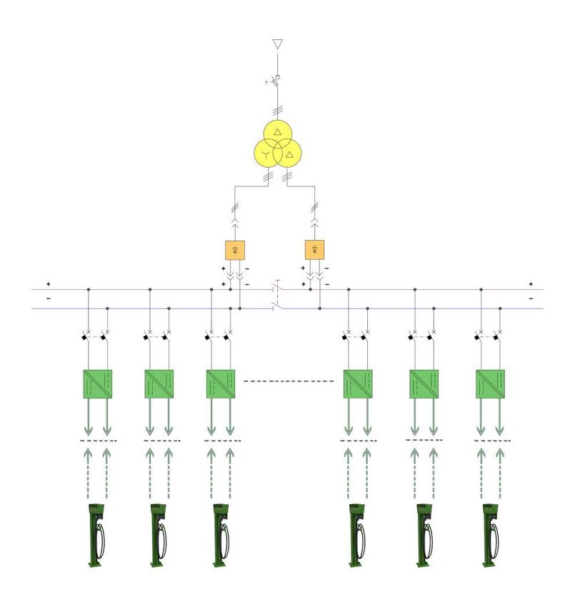
DEPOT CHARGING
RICARICA IN DEPOSITO
Depot (or Overnight) Charging is generally made by La ricarica in deposito (o ricarica notturna) è generalmente
charging the vehicle at a relatively low power (25÷100kW) effettuata caricando il veicolo ad una potenza relativamente
for a long period (2 to 5 hours).This configuration, which bassa (25÷100kW) per un lungo periodo (da 2 a 5 ore).
provides a double secondary winding transformer Questa configurazione, che prevede un trasformatore a
and two six-pulses rectifiers with a two-poles switch doppio avvolgimento secondario e due raddrizzatori a sei
operating as bus-tie, is generally proposed for systems pulsazioni con un sezionatore bipolare che funziona come
with more than 25 charging points and has the following congiuntore, è generalmente proposta per i sistemi con più
advantages: di 25 punti di ricarica e presenta i seguenti vantaggi:
- In case one of the two rectifier is out of service, - Nel caso in cui uno dei due raddrizzatori sia fuori
closing the Bus-Tie, it is possible to grant at least half servizio, chiudendo il congiuntore, è possibile erogare
of the available power. almeno la metà della potenza disponibile.
- The twelve pulses reaction supplied to the MV
- La reazione a dodici impulsi data sulla rete MV dai due
network by the two rectifiers results in a sensible
raddrizzatori si traduce in una sensibile riduzione delle
reduction of the harmonics on the line and
armoniche sulla linea e di conseguenza dei filtri armonici
consequently of the harmonic filters which could be
che potrebbero eventualmente essere evitati.
eventually avoided.
- Se il congiuntore è utilizzato come normalmente
- If the Bus-Tie Switch is operated as normally open,
aperto,i due sistemi di sbarre c.c. possono essere
the two DC busbars can be sized for half of the total
dimensionati per la metà della corrente c.c. totale.
DC current.
Per i sistemi con un massimo di 25 punti di ricarica, il
For systems with up to 25 charging points the system
sistema proposto prevede un singolo raddrizzatore a sei
proposed foresees a single six pulses rectifier.
pulsazioni.
The System is composed of the following apparatuses
Il Sistema è composto dai seguenti apparecchi valutati in
rated according to the requested power:
base alla potenza richiesta:
• Medium Voltage Switchgear
• Scomparto Interruttore di Media Tensione
• MV/LV Transformer with two secondary windings (one
in case of smaller systems) • Trasformatore MT/BT a due avvolgimenti secondari
(uno in caso di sistemi più piccoli)
• D
C Current System composed of:
- Nr.2 (1 in case of smaller systems) Six-Pulses Diode • S istema in Corrente Continua composto da:
Rectifier - 750VDC - Nr. 2 (1 in caso di sistemi più piccoli) Raddrizzatori Trifasi
- Nr.1 Two-Poles Motorized Disconnector Switch- a Diodi - 750Vcc
750Vdcoperating as Bus-Tie - Nr. 1 Sezionatore Bipolare Motorizzato - @750Vcc che
- DC Battery Charger Cabinets each composed of up opera come Congiuntore
to 5 independent insulated DC/DC Converters each - Scomparto Caricabatterie c.c. ciascuno composto di
rated 25÷100kW @ 650V and equipped with a Two- un massimo di 5 convertitori c.c./c.c. isolati indipendenti
Poles Circuit Breaker. ciascuno con potenza nominale pari a 25÷100kW @ 650V
• Low Voltage Auxiliary Service Cabinet composed of: e dotato di un Interruttore Bipolare.
- Nr. 1 Auxiliary Transformer • Armadio Servizi Ausiliari BT contenente:
- Nr. 1 UPS - Nr. 1 Trasformatore ausiliario
- Low voltage AC and DC equipment - N. 1 UPS
• Control & Supervision Cabinet: where a PLC and a - Apparecchiature in bassa tensione c.a. e c.c.
display can be housed
• Pannello di controllo e supervisione dove possono
• Charging Points each equipped with Signal Lamps essere alloggiati un PLC e un display
(optional Touch-Panel Display) and CCS – Combo2
plug • Colonnine di ricarica ciascuna dotata di lampade di
segnalazione (display touch-panel opzionale) e Presa
The whole system can be also supplied in a containerized CCS – Combo2.
solution where all the above equipment (except the
Charging Points) are installed and connected. L'intero sistema può anche essere fornito in un container
The main components of the Charging System are the in cui sono installate e collegate tutte le apparecchiature
DC Battery Charger Cabinets and the Charging Points sopra elencate (ad esclusione delle Colonnine di Ricarica).
I componenti principali del sistema di ricarica sono lo
Scomparto Caricabatterie c.c. e le Colonnine di Ricarica
4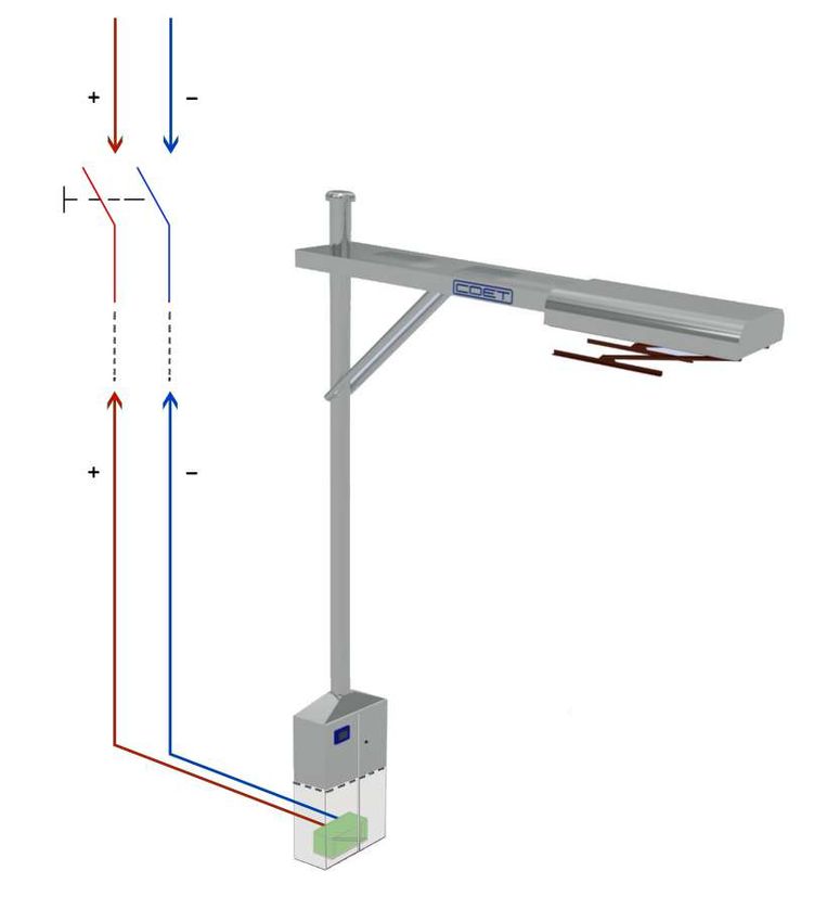
SINGLE LINE DIAGRAM FOR DEPOT CHARGING

SCHEMA UNIFILARE PER RICARICA IN DEPOSITO

         DC/DC Battery Charger
         Caricabatterie c.c./c.c.
         Colonnina di ricarica
           Charging point

                                            5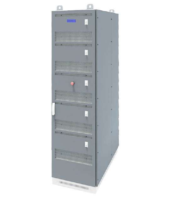
DC BATTERY CHARGER CABINET
                                                                 SCOMPARTO CARIBATTERIE C.C.

The Battery Charger Cabinets is composed of up to 5         Lo scomparto caricabatterie è composto da un numero
DC/DC converters with 25÷100kW @ 650V adjustable            massimo di 5 convertitori c.c./c.c. con uscita regolabile di
output power.                                               potenza pari a 25÷100kW @ 650V.
The battery charger is built inside a self-supporting       Il caricabatterie è costruito all'interno di una struttura
metallic structure properly treated and coated for indoor   metallica autoportante adeguatamente trattata e rivestita
installation. The cabinet is designed and manufactured      per l'installazione interna. L'armadio è progettato e
to minimize preventive and corrective actions. The power    realizzato per ridurre al minimo le azioni preventive e
section is withdrawable to grant that basic maintenance     correttive. La sezione di conversione è estraibile per
can be done in less than 30 minutes.                        garantire che l’eventuale sostituzione possa essere
Each cabinet is also provided with a CONTROL                eseguita in meno di 30 minuti.
SECTION constituted of a Touch-Screen display that          Ogni armadio è inoltre dotato di una SEZIONE DI
gathers via serial communication the converters             CONTROLLO costituita da un display Touch-Screen
parameters       (measurements and alarms) and Low          che raccoglie tramite comunicazione seriale i parametri
voltage components (like emergency push button,             dei convertitori (misure e allarmi) e da vari componenti
signalization lamps, space, heater, miniature C/Bs and      BT (pulsante di emergenza, lampade di segnalazione,
terminals)                                                  riscaldatore, Mini Interruttori e morsetti)

  6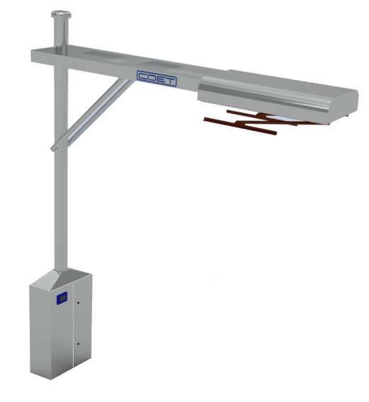
The single insulated DC/DC converter module rated Il singolo modulo di conversione c.c./c.c. isolato da
25÷100kW @ 650V is constituted of a Buck-Boost 25÷100kW @ 650V è costituito da un Convertitore c.c.
DC/DC Converter (chopper) that can grant a galvanic Buck-Boost (chopper) dotato di ingressi ed uscite c.c.
insulation between its own input and output terminals isolati galvanicamente tra loro (Schema Full-Bridge).
(Full-Bridge connection).
D.C./DC.C. Converter Block
Blocco convertitore c.c./cc.
The input and output stages are withdrawable and Le sezioni di ingresso ed uscita sono estraibili e raffreddate
forced air cooled to reduce the semiconductors and ad aria forzata raffreddata per ridurre le temperature
magnetic parts operating temperatures in order to grant di lavoro dei semiconduttori e delle parti magnetiche
high reliability and long life of the equipment; the same al fine di garantire elevata affidabilità e lunga durata
air is used also to cool the insulation transformer. dell'apparecchiatura; la stessa aria viene utilizzata anche
per raffreddare il trasformatore d'isolamento.
The converter is divided in two sections:
• POWER SECTION containing the DC chopper Il convertitore è diviso in due sezioni:
• CONTROL SECTION containing the Control and • SEZIONE
DI POTENZA contenente il Chopper c.c.
Regulation Board and Low voltage components. • SEZIONE
DI CONTROLLO contenente la Scheda di
Regolazione e Controllo e i componenti di bassa
tensione.
7CHOPPER MODULE ELECTRICAL CHARACTERISTICS
CARATTERISTICHE ELETTRICHE MODULO CHOPPER
Rated Power
25 kW 50 kW 75 kW 100 kW
Potenza nominale
Rated Input Voltage UN (EN60146-1-1 & EN61439-1)
750 Vcc
Tensione di ingresso nominale UN (EN60146-1-1 & EN61439-1)
Power Frequency Withstand Voltage Ua (EN 50123-1 Tab.1):
Tensione di tenuta a frequenza industriale
- To earth and between phases:
3,6 kV
Verso terra e tra le fasi
- Across the isolating distance
4,3 kV
Sulla distanza di sezionamento
Input Voltage Range
600 Vcc ÷ 750 Vcc
Intervallo di tensione di ingresso
Rated Output Voltage
650 Vcc
Tensione di uscita nominale
Output Voltage Range
400 Vcc ÷ 1000 Vcc
Intervallo di tensione di uscita
Rated Input Current (@ 750Vcc)
33,5 A 67 A 100,5 A 134 A
Corrente di ingresso nominale (@ 750Vcc)
Rated Output Current (@ 650Vcc)
38,5 A 77 A 115,5 154 A
Corrente di uscita nominale (@ 650Vcc)
Duty Class (IEC 60146 & EN 50328)
I
Classe di sovraccarico (IEC 60146 & EN 50328)
Connection Type
Full Bridge
Tipo di connessione
Semiconductor Type
IGBT (o TIRISTORI)
Tipo di semiconduttori
Total Loss at Rated Power
< 750 W < 1,5 kW < 2,2 kW < 3kW
Perdite totali a potenza nominale
Cooling
AF
Raffreddamento
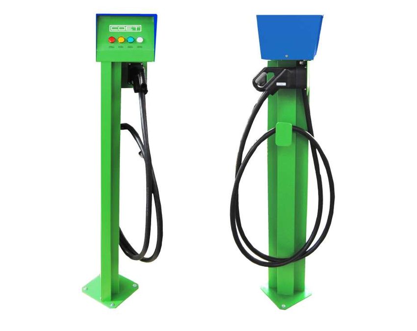
8CHARGING POINT
COLONNINA DI RICARICA
Whatever is the size of the Charging System, each of the Qualunque sia la dimensione del sistema di ricarica,
independent DC Outputs of the converters is connected ciascuna delle uscite c.c. indipendenti dei convertitori e
to a “charging point” that allows the connection to the connessa ad una "colonnina di ricarica" che permette il
vehicle and is provided with: collegamento al veicolo ed è composta da:
• Nr. 1 Signalization Lamps (optional Touch-Panel • Lampade di segnalazione Nr. 1 (display Touch-Panel
Display) for recharge status local visualization opzionale) per la visualizzazione locale dello stato di
• Nr. 1 Charging Protocol/Canbus/Ethernet Converter ricarica
• Nr. 1 CCS-Combo 2 plug • Nr. 1 Convertitore Protocollo di ricarica/ Canbus/
Ethernet
• Compliant with ISO15118 / DIN 70121 / IEC 61851-23 &
-24 • Nr. 1 Presa CCS-Combo 2
• OCPP Compliant • Conforme a ISO15118 / DIN 70121 / IEC 61851-23 & -24
• Conforme a OCPP
Front view Side view
Vista frontale Vista laterale
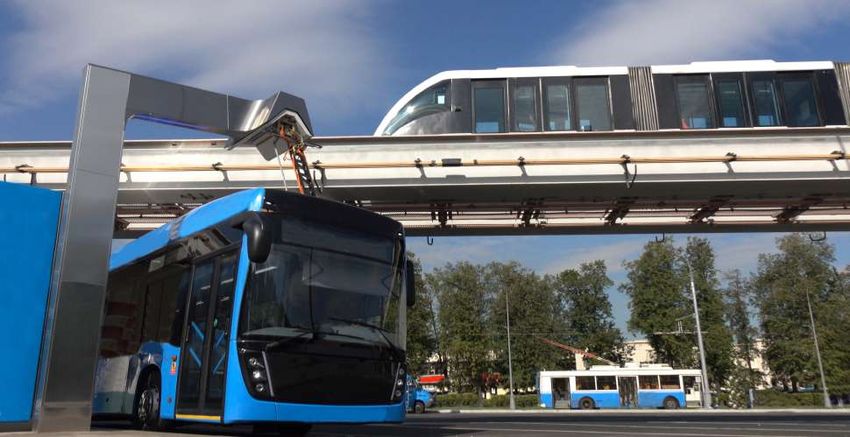
9WAYSIDE CHARGING
RICARICA A BORDO STRADA
Wayside (or Opportunity) Charging is generally done La ricarica a bordo strada (o Ricarica Rapida) viene
during daily operation at any given stop or rest generalmente effettuata durante il funzionamento
opportunity charging the vehicle at a high power quotidiano a qualsiasi fermata di servizio o di riposo
(200÷600kW) for a very short period (3 to 20 minutes). caricando il veicolo ad alta potenza (200÷600kW) per un
periodo molto breve (da 3 a 20 minuti).
In this configuration the System is composed of the
following apparatuses rated according to the requested Nella configurazione il Sistema è composto dai seguenti
power: apparati valutati in base alla potenza richiesta:
• D
C Current System composed of: • S istema in Corrente Continua composto da:
- Nr. 1 Two-Poles Motorized DC Load Break Switch - Nr. 1 Sezionatore c.c. Sottocarico Bipolare Motorizzato
(generally pole-mounted) (generalmente montato su palo)
- Nr. 1 DC Battery Charger with DC/DC Converters - Nr. 1 Carica Batterie c.c. composto da Convertitori c.c.
rated 200÷600kW @ 650V and equipped with a Two- con potenza nominale pari a 200÷600kW @ 650V e
Poles DC Circuit Breaker. dotato di un Interruttore Bipolare.
• Low Voltage Auxiliary Service Section composed of: • Sezione Servizi Ausiliari BT composta da:
- Nr. 1 DC/DC Aux Supply - Nr. 1 Alimentatore Ausiliario c.c./c.c.
- Nr. 1 UPS - N. 1 UPS
- Low voltage AC and DC equipment - Apparecchiature in bassa tensione c.a. e c.c.
• Control & Supervision Section: where can be housed a • Sezione di controllo e supervisione dove possono
PLC and a display essere alloggiati un PLC e un display.
• Opportunity Charger equipped with Upside-Down • Opportunity Charger (o Palo Pantografo) dotato di
Pantograph Pantografo a discesa (upside-down).
The whole system (except the DC Load-Break Switch) L'intero sistema (ad eccezione del Sezionatore c.c.
is generally supplied either integrated in the basement sottocarico) è generalmente fornito o integrato nella base
of the Opportunity Charger Mast (up to 200kW) or in a dell’Opportunity Charger (per potenze fino a 200kW) o in
single frame solution for outdoor installation where all un unico quadro per esterno in cui sono installate e
the above equipment (except the Opportunity Charger) collegate tutte le apparecchiature sopra elencate (ad
are installed and connected. esclusione dell’Opportunity Charger).
The main components of the Charging System are the I componenti principali del sistema di ricarica sono il
DC Battery Charger and the Opportunity Charger Caricabatterie c.c. e l’Opportunity Charger
10SINGLE LINE DIAGRAM FOR WAYSIDE CHARGING
SCHEMA UNIFILARE PER RICARICA A BORDO STRADA
Opportunity charger
Opportunity charger
DC / DC Converter
Convertitore c.c. / c.c.
11WAYSIDE DC BATTERY CHARGER
RICARICA DI BORDO C.C.
The DC Battery Charger is composed of one DC/DC Il caricabatterie è composto da un convertitore c.c./c.c. con
converter with 200kW @ 650V adjustable output power. uscita regolabile di potenza pari a 200kW @ 650V. Potenze
Higher Recharging Powers are obtained connecting in di ricarica maggiori si raggiungono collegando in parallelo
parallel more 2 or 3 converters. 2 o 3 convertitori.
The architecture of the battery charger is essentially the L'architettura del caricabatterie è sostanzialmente la
same of the Depot Battery Charger with the only stessa del dello Scomparto Caricabatterie da Deposito
difference that the frame is designed for outdoor con l'unica differenza che il telaio è progettato per
installation. l'installazione esterna.
The single DC/DC converter module rated 200kW @ Il singolo modulo di conversione c.c./c.c. da 200kW @ 650V
650V is constituted of a Buck-Boost DC/DC Converter è costituito da un Convertitore c.c. Buck-Boost (chopper)
(chopper) that can grant galvanic insulation between its dotato di ingressi ed uscite c.c. isolati galvanicamente tra
(own) input and output terminals. loro (Schema Full-Bridge).
The architecture is essentially the same of the single L'architettura è essenzialmente la stessa del singolo
DC/DC converter module rated 25÷100kW @ 650V modulo di conversione c.c./c.c. da 25÷100kW @ 650V.
12200 KW CHOPPER MODULE ELECTRICAL CHARACTERISTICS
200 KW CARATTERISTICHE ELETTRICHE MODULO CHOPPER
Rated Power 200 kW
Potenza nominale
Rated Input Voltage UN (EN60146-1-1 & EN61439-1)
750 Vcc
Tensione di ingresso nominale UN (EN60146-1-1 & EN61439-1)
Power Frequency Withstand Voltage Ua (EN 50123-1 Tab.1):
Tensione di tenuta a frequenza industriale
- To earth and between phases:
3,6 kV
Verso terra e tra le fasi
- Across the isolating distance
4,3 kV
Attraverso la distanza di sezionamento
Input Voltage Range
600 Vcc ÷ 750 Vcc
Intervallo di tensione di ingresso
Rated Output Voltage
650 Vcc
Tensione di uscita nominale
Output Voltage Range
400 Vcc ÷ 750 Vcc
Intervallo di tensione di uscita
Rated Input Current (@ 750Vcc)
270 A
Corrente di ingresso nominale (@ 750Vcc)
Rated Output Current (@ 650Vcc)
310 A
Corrente di uscita nominale (@ 650Vcc)
Duty Class (IEC 60146 & EN 50328)
I
Classe di sovraccarico (IEC 60146 & EN 50328)
Connection Type
Full Bridge
Tipo di connessione
Semiconductor Type
IGBT (o TIRISTORI)
Tipo di semiconduttori
Total Losses at Rated Power
< 6 kW
Perdite totali a potenza nominale
Cooling
AF
Raffreddamento
13OPPORTUNITY CHARGER
OPPORTUNITY CHARGER
The Opportunity Charger, directly connected to the DC L'Opportunity Charger, direttamente collegato all’uscita
Output of the converter, provides the connection to the c.c. del convertitore, fornisce il collegamento al veicolo per
vehicle for recharging during daily operation at the la ricarica durante il funzionamento quotidiano alle fermate
chosen way side stops. prescelte.
Each Opportunity Charger is equipped with: Ciascun Opportunity Charger è dotato di:
• Nr. 1 DC/DC Battery Charger integrated in the mast • Nr. 1 DC/DC Battery Charger integrato nella base per
if rated up to 200kW @ 650V; for higher power the potenze fino a 200kW @ 650V; per potenze superiori
converter is housed in a separate cabinet generally il convertitore è alloggiato in un quadro per esterne
placed nearby the Opportunity Charger. separato generalmente collocato nelle vicinanze del
• Nr. 1 Touch-Panel Display for recharge status and Opportunity Charger.
parameters local visualization • Nr. 1 Touch-Panel Display per la visualizzazione locale
• Nr. 1 Charging Protocol/Canbus/Ethernet Converter dello stato e dei parametri di ricarica
• Nr. 1 Upside-Down Pantograph • Nr. 1 Convertitore Protocollo di ricarica/ Canbus/
Ethernet
• Compliant with ISO15118 / DIN 70121 / IEC 61851-23 &
-24 • Nr. 1 Pantografo a discesa (upside-down).
• OPP-Charge Protocol and OCPP Compliant • Conforme a ISO15118 / DIN 70121 / IEC 61851-23 & -24
• Conforme ai Protocolli OPP-Charge e OCPP
14COET S.p.A. +39 02 842934 www.coet.it coet@coet.it Via Civesio, 12 - 20097 San Donato Milanese (MI) - Italia
Puoi anche leggere