Kobra SSD - Libretto istruzioni Operating Instructions Betriebsanleitung Mode D'emploi - Evolution Demo Store
←
→
Trascrizione del contenuto della pagina
Se il tuo browser non visualizza correttamente la pagina, ti preghiamo di leggere il contenuto della pagina quaggiù
Kobra SSD

Libretto istruzioni
Operating Instructions
Betriebsanleitung
Mode D’emploi
SOMMARIO
Indice…………………………………………………..pag.1

Importanti informazioni per la sicurezza………..… pag.3

Imballo e vista generale…………………………….. pag.4-5

Installazione…………………………………………. pag.6

Materiali distruttibili……………………………….              pag.7

Avvio e funzionamento………………………………pag.8

Manutenzione………………………………………. .pag.9

Rimontaggio rotore centrale e lame di taglio………pag.13/15

Istruzioni affilatura lame di taglio e rotore ………. ..pag.16/17

Schema elettrico……………………………………. ..pag.18/19

Dichiarazione di conformità…………………………..pag.21

                                                      1
AVVERTENZE – IMPORTANTE – PERICOLO
PRIMA DELLA MESSA IN MARCIA DELL’ APPARECCHIO BISOGNA LEGGERE ATTENTAMENTE LE ISTRUZIONI SULL’ USO E LE
SEGUENTI AVVERTENZE
Prima di collegare l’ apparecchio fare attenzione che il voltaggio e la frequenza di rete corrispondano ai dati di targa
posta sulla macchina.
Per l’utilizzo della macchina si consiglia l’uso di protezioni individuali:cuffie anti-rumore,guanti e occhiali protettivi.
Far funzionare la macchina solo con contenitore di raccolta frammenti correttamente inserito.
TOGLIERE TENSIONE ALLA MACCHINA NEI SEGUENTI CASI:
Prima di svuotare il contenitore di raccolta Prima di accedere ai motori elettrici
frammenti Prima di accedere alla camera di distruzione e di
Prima di accedere al pannello elettrico effettuare la sostituzione delle lame di taglio
Prima di accedere al bidone di aspirazione Prima di effettuare la pulizia della griglia
delle polveri
CONSULTARE IL MANUALE
ATTENZIONE!
PRECAUZIONI DI SICUREZZA
TENERE LONTANO
DALL’IMBOCCO CRAVATTE O ALTRI PENDENTI
NON METTERE LE MANI NELL’IMBOCCO DEL
GRUPPO DI TAGLIO
NON LASCIARE UTILIZZARE L’APPARECCHIO
AI BAMBINI
TENERE LONTANO DALL’IMBOCCO
CAPELLI LUNGHI
NON USARE PRODOTTI O LUBRIFICANTI AD AEREOSOL
2IMPORTANTI INFORMAZIONIPER LA SICUREZZA
UTILIZZO IN SICUREZZA
Il costruttore declina ogni responsabilità per eventuali danni a persone e/o cose, causati dalla non osservanza di quanto è riportato nel
manuale di uso e manutenzione.
Il distruttore KOBRA SSD è progettato e costruito con protezioni meccaniche e dispositivi di sicurezza atti a proteggere l’operatore da
possibili danni fisici.
È tassativamente vietato modificare o rimuovere i ripari, i dispositivi di sicurezza e le etichette di attenzione, nel caso l’operatore decida
di apportare modifiche è da intendersi sotto la propria responsabilità, declinando sin da ora il costruttore da eventuali danni fisici
causati da un utilizzo improprio, le attrezzature sono considerate conformi alla normativa solo se non modificate, le Norme
comportamentali sui luoghi di lavoro sono a carico dell’acquirente e tutte le operazioni di manutenzione ordinaria e straordinaria non
prevista dalla garanzia, sono da considerare sotto la propria responsabilità.
Il Costruttore garantisce il pieno rispetto delle normative vigenti in materia di rischio elettrico e rischio meccanico.
Rischi residui
L’attrezzatura deve essere utilizzata da personale formato preventivamente. (IMPORTANTE)
Un mezzo “intrinsecamente” sicuro non esiste, così come non esiste il lavoratore che, con l’attenzione può “sempre” evitare l’incidente.
Pertanto, NON sottovalutate i rischi connessi all’uso della macchina e concentratevi sul lavoro che state svolgendo onde evitare anche
danni materiali.
Rischi connessi all’uso della macchina
Nonostante il distruttore KOBRA SSD non è da considerarsi un’apparecchio particolarmente pericoloso, occorre non sottovalutare i
rischi connessi all’uso della attrezzatura stessa, seppur il costruttore con l’applicazione di tutti i dispositivi di sicurezza per un uso
sicuro della macchina, ne garantisce la conformità.
La formazione verbale all’utilizzo della attrezzatura, ad ogni operatore che viene incaricato sia per l’uso sia per la manutenzione, non
declina anche dalla lettura del libretto di uso e manutenzioni.
Rischio elettrico
I lavori all’impianto elettrico della macchina devono essere eseguiti solo ed esclusivamente da personale specializzato ed autorizzato
dal costruttore, se la manutenzione verrà affidata a personale esterno sarà necessario appurare che l’operatore abbia una formazione
specifica sulle manutenzioni di attrezzature ed impianti elettrici, dovrà conoscere dove sono posizionate, le linee dell’alimentazione
elettrica e mantenere una certa distanza da esse, dovrà rilasciare a fine lavori un certificato di conformità.
I lavori sotto tensione sono vietati.
Gli addetti all’utilizzo del distruttore, salvo non abbiano effettuato specifica formazione, non DEVONO effettuare nessuna
manutenzione. Non modificate, in nessun modo, l’impianto elettrico della macchina. Qualsiasi tentativo a tale riguardo, può
compromettere il funzionamento dei dispositivi elettrici provocando, in tal modo, malfunzionamenti o incidenti e invalidando la garanzia.
Avvertimenti
Se sentite dei rumori insoliti o avvertite qualcosa di strano, spegnete l’apparecchio e date immediatamente comunicazione
al responsabile che provvederà ad avviare la procedura di manutenzione.
Non intervenite mai durante il funzionamento del distruttore su organi in movimento.
Durante tutte le fasi si raccomanda la massima cautela in modo da evitare danni a persone, cose o alla macchina stessa.
Terminato il lavoro, pulite l’area di lavoro e ad attrezzatura spenta, provvedete a rimuovere materiale superfluo.
Prima dello spegnimento della attrezzatura controllate la sua efficienza per evitare che altri operatori si trovino una
macchina non perfettamente funzionante al successivo utilizzo.
Verificate che i tecnici utilizzino solo ricambi originali.
Il distruttore KOBRA SSD ha prestazioni ben definite, non chiedete all’attrezzatura lavori di distruzione per i quali non è stata
progettata.
Quando il distruttore KOBRA SSD rimane inattivo per lunghi periodi, disinserite il cavo di alimentazione dalla rete elettrica.
I posti di lavoro vanno mantenuti puliti ed ordinati, il disordine è causa di incidenti ed infortuni.
Attenzione:
Attendere almeno 30 secondi dopo aver introdotto materiale da distruggere all’interno della camera di distruzione, prima di premere il
pulsante STOP e arrestare la macchina ,onde evitare di bloccare il gruppo superiore all’avviamento successivo.
Attenzione:
Attendere che il gruppo superiore abbia distrutto tutto il materiale introdotto all’interno della camera di distruzione,prima di inserire altro
materiale da distruggere.
Importante:
Per l’utilizzo della macchina si consiglia l’uso di protezioni individuali:cuffie anti-rumore,guanti e occhiali protettivi.
3IMBALLO
La macchina viene fornita imballata sopra un bancale di legno per garantirne l’integrita’ durante il trasporto.
Munirsi di:
- Martello
- Carrello elevatore con capacità minima di 800 Kg
- Tenaglia o forbici
- Chiave esagonale da 13
1) Tagliare la reggia e rimuovere il cartone.
Strumenti necessari: forbici o tenaglie
2) Rimuovere il bancale superiore
3) Rimuovere le staffe di trasporto laterali
Strumenti necessari: Chiave esagonale da 13
4) Rimuovere il modello KOBRA SSD dal bancale.
Strumenti necessari: Carrello elevatore
Attenzione!!! Il modello KOBRA SSD deve essere sollevato
dal bancale con il carrello elevatore dalla parte
anteriore destra
Il modello KOBRA SSD è dotato di ruote per facilitare la maneggevolezza e quindi il suo posizionamento.
Per posizionare il modello KOBRA SSD accertarsi che le ruote anteriori siano sbloccate .
La manovra di posizionamento è consigliata che venga effettuata almeno da due persone.
NON spingere la macchina su una superficie inclinata,questo potrebbe far perdere il controllo
dell’apparecchio stesso e causare danni o lesioni personali.
45
INSTALLAZIONE
Per apparecchi con presa scollegabile,utilizzare una          Se il senso di rotazione dei coltelli di taglio risultano
presa facilmente accessibile e nelle vicinanze                contraria a quella indicata in figura,far modificare da
dell’apparecchio stesso.                                      un ELETTRICISTA QUALIFICATO la sequenza dei
Per la sua installazione e messa in funzione è                cavi R-S-T sulla presa del cavo di alimentazione del
necessaria la presenza di un elettricista qualificato,        Vostro apparecchio.
che partendo da una linea elettrica trifase presente
nella Vostra azienda, esegua il collegamento                  Il modello KOBRA SSD puo’ essere collocato in un
elettrico.                                                    area entro 4 metri da una presa di corrente a muro.
Il modello KOBRA SSD viene fornito completamente              Si raccomanda si posizionare la macchina a
cablato e corredato di cavo quadripolare+terra per le         80/100mm dalla parete per una corretta
versioni 380-415V,mentre viene fornito con cavo               ventilazione.
tripolare+terra,per le versioni 208V
(USA,CANADA),a tale cavo occorre collegare una
spina a norme e normalmente in uso nel paese dove
verra’ istallato l’apparecchio.
Linea da 32 Amps per macchine a 380-415 Volts e
linea da 50 Amps per macchine a 208 Volts (USA e
CANADA).
Collegate il cavo di alimentazione del Vostro
modello KOBRA SSD alla rete elettrica.
NOTE
L’ impianto elettrico a cui il modello KOBRA SSD
deve essere collegato, deve essere fornito di
interruttore differenziale per la protezione contro i
guasti di terra per i circuiti primari.
Sul pannello di comando del Vostro apparecchio è
presente un interruttore generale , ruotare la leva
dalla posizione “0” alla posizione “1” e verificate che
la spia “STAND-BY” sul pannello di comando sia
accesa, premere il pulsante FORWARD sul
pannello di comando .
Ora il Vostro distruttore è in funzione.

Attenzione!! Controllate visivamente mediante la
rimozione dell’apposito sportello d’ispezione posto
sul fianco dx del vostro distruttore ,che i coltelli di
taglio ruotino in senso orario come indicato in figura.

                                                          6
MATERIALI DISTRUTTIBILI E PREPARAZIONE DEL MATERIALE
Il modello KOBRA SSD NON è adatto alla distruzione di Hard Disk a supporto magnetico rotazionali.
Il modello KOBRA SSD è in grado di distruggere i seguenti materiali:
- Cellulari
- Tablet
- CD/DVD
- Penne USB
- Circuiti elettronici
- Memorie SSD
Attenzione! Batterie,relay,condensatori,coperchi metallici e display a cristalli liquidi vanno rimossi dai
supporti prima che vengano distrutti.
Questo comporta la preparazione del materiale prima della distruzione.
NOTA! Il materiale distrutto e/o separato deve essere smaltito in modo appropriato secondo le normative
vigenti nel proprio paese.
7AVVIO E FUNZIONAMENTO
Leggere attentamente questo paragrafo! Intasamenti
Nel caso in cui avviene un’intasamento , si illumina
La maggior parte dei problemi si verificano durate le la spia “JAM” e la spia “STOP FEEDING”sul
prime ore di funzionamento dell’apparecchio. pannello di controllo,la macchina si arresta e inverte
Questi problemi si possono risolvere ed evitare solo immediatamente la rotazione dei rulli di taglio e
dopo una attenta lettura del presente manuale successivamente si arresta.
Attenzione! La distruzione di materiale NON idoneo Controllare visivamente i due gruppi di taglio come
potrebbe causare inceppamenti o gravi danni segue:
all’apparecchio.
Gruppo superiore
Procedura di verifica: - Togliere alimentazione alla macchina.
Si consiglia prima di avviare il vostro distruttore di - Aprire la torretta superiore di
familiarizzare con i comandi posti sul pannello di copertura tramite serratura a chiave.
controllo. - Liberare il gruppo.
- assicurarsi che tutte le protezioni - Richiudere la torretta superiore.
e/o porte siano chiuse.
- Assicurarsi che all’interno della Gruppo inferiore
camera di distruzione non ci sia - Togliere alimentazione alla macchina.
materiale NON distrutto - Aprire la porta anteriore, svitare il
pomello della paratia di ispezione.
Procedura di avvio: - Liberare il gruppo.
1) Dopo aver collegato l’apparecchio alla rete - Richiudere la paratia di ispezione.
elettrica,ruotare l’interruttore generale “0/1” dalla - Chiudere la porta anteriore.
posizione “0” alla posizione “1” posto sul pannello Eseguire nuovamente le “Procedure di avvio” per
di controllo. riavviare la macchina.
Una volta che l’interruttore è in posizionato “1” si
accende la spia “STAND-BY” posta sul pannello
di controllo. Procedura di arresto:
2) Premere il pulsante “FORWARD” e il Vostro Dopo aver introdotto l’ultimo oggetto da distruggere
distruttore avvia automaticamente i gruppi di attendere circa 30 secondi prima di premere il tasto
taglio. “STOP”posto sul pannello di controllo.
Per spegnere l’apparecchio ruotare l’interruttore
Procedura di alimentazione e di funzionamento: generale dalla posizione “1” alla posizione “0”.
- Inserire il materiale da distruggere nella bocca di Importante!
entrata posta sopra la torretta superiore,facendo in caso di emergenza premendo il tasto
attenzione a non sovraccaricare la camera di “EMERGENCY STOP” si arrestano tutte le funzioni
distruzione (tempo di attesa circa 30 secondi della macchina.
prima di inserire nuovamente materiale da
distruggere) onde evitare intasamenti
e quindi il blocco del gruppo di taglio superiore.
Se viene introdotto del materiale da distruggere
troppo velocemente all’interno della bocca di
entrata,si potrebbe causare degli inceppamenti.
Attenzione!! NON introdurre materiale non
idoneo alla distruzione,questo potrebbe
provocare danni o inceppamenti
L’introduzione di materiale non idoneo invalida
la garanzia.
8MANUTENZIONE
Prima di effettuare operazioni di manutenzione e riparazioni o di intervenire sulle parti interne della
macchina, scollegare la spina di alimentazione della rete elettrica.
Pulizia:
L’apparecchio è dotato di un contaore (vedi figura “B”) che deve essere monitorato per assicurare la
manutenzione necessaria come qui di seguito riportato:
Ogni 8 ore di funzionamento:
- aprire la torretta superiore e rimuovere eventuali detriti che si sono depositati sui coltelli di taglio/pettini o
sulle pareti della camera di distruzione.
- Ispezionare visivamente i coltelli di taglio per eventuali danni.
- Aprire la porta anteriore e svuotare il contenitore raccolta frammenti.
- Griglia (figura “A”):
Svitare il pomello, abbassare il supporto griglia ed estrarre la griglia come indicato in figura “A”.
Rimuovere eventuali detriti depositati sulla griglia ed ispezionare visivamente l’integrità della griglia stessa
da eventuali danni riportati.
- Riposizionare la griglia sul supporto griglia e richiudere con il pomello.
- Pulire i detriti in eccesso all’interno dell’area di raccolta frammenti.
- Pulire tutte le superfici all’interno dell’area raccolta frammenti ed esternamente alla macchina con un
panno umido.
Lubrificazione: Comunque è buona norma lubrificare quotidianamente con olio KOBRA il gruppo di taglio
superiore per garantire massima efficienza distruttiva e durata nel tempo del gruppo di taglio.La
lubrificazione deve essere eseguita manualmente immettendo olio KOBRA all’interno della camera di
distruzione del gruppo superiore come indicato in figura “A”.
ATTENZIONE! Si raccomanda l’uso di guanti e occhiali!
ATTENZIONE! Per la pulizia non usare mai olio sintetico, prodotti a base di benzine o lubrificanti ad
aereosol di nessun tipo all’interno dell’apparecchio o nelle sue vicinanze.
FIGURA “B” FIGURA “A”
9FILTRO HEPA ( FIGURA “A”) Figura “A”
Il fitro HEPA richiede una manutenzione
periodica.
Il filtro HEPA deve essere sostituito almeno una
volta all’anno.
NOTA! La mancata sostituzione del filtro HEPA può
causare emissioni di particelle dannose.
Verifica filtro HEPA:
Dopo aver collegato l’apparecchio alla rete
elettrica,ruotare l’interruttore generale “0/1” dalla
posizione “0” alla posizione “1” posto sul pannello
di controllo.Una volta che l’interruttore è in posizione
“1” si accende la spia “STAND-BY” posta sul
pannello di controllo.
Premere il pulsante “FORWARD” e il Vostro
distruttore si avvia automaticamente.
Aprire la porta laterale e verificare che la spia “A”
posta sopra l’aspiratore sia spenta, se accesa
spegnere l’apparecchio e pulire il filtro e svuotare il
contenitore come segue:
NOTA! Prima di pulire o sostituire il filtro HEPA
usare guanti e mascherina.
- - Aprire la portina laterale
- - Estrarre l’aspiratore.
- - Rimuovere il corpo testata “B” dell’aspiratore
- rilasciando i due ganci di fissaggio.
- Rimuovere cartuccia filtro HEPA “C” svitando le Figura “B”
viti “E”
- Inserire il filtro in un sacchetto di plastica come
raffigurato in figura “B”,chiudere
scrupolosamente il sacchetto e battere con la
mano o sul pavimento 3 – 4 volte il filtro affinchè
possa essere pulito dalla polvere.Ripetere
questa operazione fino ad ottenere un filtro
pulito.
- Inserire nuovamente la cartuccia filtro
nel’apposita sede del corpo testata
dell’aspiratore.
- Svuotare il contenitore “D” dell’aspiratore.
- Chiudere il corpo testata e rimettere l’aspiratore
all’interno del vano.
- Chiudere la portina e riavviare l’apparecchio.
.
10VERIFICA TENSIONAMENTO CINGHIE
Rimuovere la copertura laterale destra della macchina.
Verificare che le cinghie abbiano un movimento compreso tra 10-15mm nella parte centrale come indicato
in figura.
TENSIONAMENTO CINGHIE (figura “C”)
SE OCCORRE TENSIONARE LE CINGHIE:
- Rimuovere la copertura laterale destra e posteriore della macchina.
- Allentare le viti “A” e il dado “B”,avvitare le viti “C” quindi verificare che le cinghie abbiano un
movimento compreso tra 10-15mm nella parte centrale.
- Avvitare il dado “B” e serrare le viti “A”.
- Riposizionare la copertura laterale destra e posteriore della macchina.
Figura “C”
11VERIFICA ROTORE CENTRALE E LAME DI TAGLIO
(gruppo inferiore)
Periodicamente è consigliato verificare visivamente l’integrità del rotore centrale e delle lame di taglio come
segue:
- Aprire la portina anteriore “A”
- Avvitare le Barre di sicurezza “G” con le viti in dotazione come indicato in figura.
- Svitare la vite “B” di bloccaggio del gruppo.
- Estrarre il gruppo inferiore “C” come indicato in figura.
- Ispezionare visivamente l’integrità del rotore centrale “D”,verificare il filo di taglio del rotore
centrale se presenta usura eccessiva ,grossi segni di rottura , crepe profonde , ecc..
- Rimuovere la griglia “E” svitando il pomello e abbassando il supporto griglia.
- Ispezionare visivamente l’integrità delle lame di taglio fisse come indicato in figura
“F”,quindi verificare il filo di taglio delle lame se presenta usura eccessiva ,grossi segni di
rottura , crepe profonde, ecc…
A verifica ultimata , se il rotore centrale e le lame di taglio non necessitano di manutenzione straordinaria
(affilatura) riposizionare come segue:
- Riposizionare la griglia “E” sul supporto griglia quindi serrare con il pomello.
- Spingere il gruppo centrale fino a fondo corsa e serrarlo con la vite “B” di fissaggio.
- Rimuovere le Barre di sicurezza “G”
- Riposizionare il contenitore di raccolta frammenti e richiudere la portina anteriore.
12RIMOZIONE ROTORE CENTRALE
Se durante la verifica di integrità del rotore centrale si dovesse presentare la necessità di affilatura del
rotore stesso procedere come segue:
- Rimuovere le flange “A” svitando le viti di fissaggio.
- Avvitare due viti da M10 x 80 “B” per avere una maggiore presa,quindi rimuovere il rotore
centrale tirando come indicato in figura.
NOTA! E’ necessario che questa operazione venga effettuata da personale qualificato e da almeno due
persone.
RIMONTAGGIO ROTORE CENTRALE
Ad affilatura ultimata rimontare il rotore centrale come segue:
- Posizionare il rotore centrale allineando la sede chiavetta “A” con la chiavetta “B” posta
sull’albero supporto.
- Spingere fino a fondo corsa il rotore centrale
- Rimuovere le viti “C”.
- Riposizionare le flange con l’ordine rappresentato in figura (1-2-3-4) e serrarle con le viti
precedentemente rimosse.
NOTA! E’ necessario che questa operazione venga effettuata da personale qualificato e da almeno due
persone.
13RIMOZIONE LAME DI TAGLIO
Se durante la verifica di integrità delle lame di taglio si dovesse presentare la necessità di affilatura delle
lame stesse procedere come segue:
- Rimuovere le viti “A” di fissaggio.
- Rimuovere i supporti lame “B” e lame di taglio “C” come indicato in figura.
NOTA! E’ consigliabile che questa operazione venga effettuata da personale qualificato.
SECONDO GRUPPO
14RIMONTAGGIO LAME DI TAGLIO
Ad affilatura ultimata rimontare le lame di taglio come segue:
- Posizionare le lame di taglio e i supporti delle lame come indicato in figura.
- Fissare le lame e i supporti con le viti di fissaggio prestando attenzione a non serrare
completamente.
- Utilizzare le viti di regolazione per regolare la distanza esatta 0.2 mm circa (visibile tramite
sportello dì ispezione) tra rotore centrale e lame di taglio.
- A distanza regolata serrare a fondo le viti di fissaggio delle lame di taglio.
- Serrare con la vite di fissaggio lo sportello di ispezione.
SCHEMA DI MONTAGGIO LAME DI TAGLIO
15ISTRUZIONI AFFILATURA ROTORE CENTRALE
16ISTRUZIONI AFFILATURA LAME DI TAGLIO
17SCHEMA ELETTRICO 220V-60Hz
SCHEMA ELETTRICO 220V-60Hz
PE
MARRONE
BLU
T
L1 R NERO
L2 S NERO
L3 T NERO
I.G.
BLU
R S T
1L1 3L2 5L3 1L1 3L2 5L3
T.R. A1 A1
N.C
AVANTI
N.C
TA 2/T1 4/T2 6/T3
A2
2/T1 4/T2 6/T3
A2
T.R.
CONTA ORE ROSSO
BLU RETRO
BLU
NERO
BLU
NERO
NERO
BIANCO
BIANCO
R
R NERO
S NERO
MARRONE
T NERO
BIANCO
3 ph
MOTORE GRUPPO INFERIORE ASPIRATORE
BLU
STOP N.C. BIANCO
BLU
BIANCO
MARRONE
MARRONE
RETE
MARRONE L BLU
PORTA 1
PORTA 2
PORTA 3
NEON Porta aperta
BLU
BLU
BIANCO NEON Intasamenti
BLU
BLU
ROSSO N BLU
NEON stop carta
BLU
BIANCO AVANTI
2° GRUPPO
FORW. ROSSO
REV.
GIALLO
MARRONE RETE STOP
COM.
VERDE
L
NERO
BLU
BIANCO
RETRO
2° GRUPPO
ROSSO
Timer
BIANCO
BIANCO 1° GRUPPO
TA
BIANCO
AVANTI
ENCODER
superiore
TERMICA
NERO 1° GRUPPO ENCODER
inferiore
RETRO
RETE
L
Cod.27.149
MOTORE GRUPPO SUPERIORE ROSSO
ENCODER
NERO
BIANCO
MARRONE PULSANTI
VERDE
18
18PE
T
R NERO
L1
S NERO
L2
T NERO
L3
N1 BLU
N
I.G.
ROSSO GRIGIO
BLU
BLU
TELERUTTORE 1L1 3L2 5L3 TELERUTTORE 1L1 3L2 5L3
FORWARD A1 REVERSE A1
N.C
N.C
A2 A2
2/T1 4/T2 6/T3 2/T1 4/T2 6/T3
CONTAORE NERO
BLU
GRIGIO
MARRONE
BLU
TA-AMP
NERO
NERO
NERO
BLU
19
19
MARRONE
STAND-BY
ASPIRATORE
ENCODE R
Porta 1 Porta 3
BIANCO
Neon
Porta 2 porta aperta BIANCO
Rete
L
BLU
NERO
Neon
ROSSO
intasamento
BLU
MOTORE N
VERDE
3 ph SECONDO GRUPPO ROSSO
Neon
Stop carico
AVANTI
ROSSO
MARRONE 2° GRUPPO
Rete
L
FORW.
ROSSO
REV. GIALLO
RETRO STOP
VERDE
2° GRUPPO
COM. NERO
STOP N.C. 1°GRUPPO
Timer
AVANTI TA
termica BIANCO
motore
BIANCO SCHEDA ELETTRONICA
MARRONE ROSSO Encode r
SCHEMA ELETTRICO 380V-50Hz
BIANCO inferiore
RETRO ELCOMAN COD.27.149
NERO
L
1°GRUPPO
RETE
AEC Cod.366.1
SCHEMA ELETTRICO 380V-50Hz
MOTORE
PRIMO GRUPPOELECTRICAL SET-UP
SET-UP VALUES
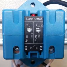
Electrical supply: Electrical supply: Electrical supply:
MODEL 380/400V 50Hz 220V 50/60Hz 200V 50/60Hz (JAPAN)
In % = 18 In % = 30 In % = 30
Delay = 0 Delay = 0 Delay = 0
FRER Delay In %
XAC032050XMC
20DICHIARAZIONE DI CONFORMITA’
In accordo con: - direttiva LVD 2014/35/UE
- direttiva 2011/65/CE
- direttiva 2014/30/UE
Il costruttore : ELCOMAN SRL
VIA GORIZIA,9
20813 BOVISIO MASCIAGO (MI) - ITALY
Dichiara con la presente che i distruttori sotto descritti sono conformi alle norme della direttiva
LVD 2014/35/UE
KOBRA serie: Kobra SSD
Le norme applicate sono:
EN 60950-1:2006/A11:2009/A1:2010/A12:2011/A2:2013 EN 61000-3-2 :2014
EN 61000-3-3 :2013
EN 55014-1 :2006+A1 :2009+A2 :2011
EN 55014-2 :1997+A1 :2001+A2 :2008
Bovisio Masciago, 20.11.17
A.De Rosa
Ufficio tecnico
21SUMMARY
Contents……………………………………………..page 22
Important safety information……………………….page 24
Packaging and general overview……..…………..page 25-26
Installation………………………………………….. page 27
Shreddable materials ………………………….. page 28
Startup and operation…………………………… page 29
Maintenance………………………………………. .page 30
Assembly of central rotor and cutting mechanism …page 34/36
Instructions for sharpening cutting mechanism and rotor…page 37/38
Electrical diagram…………………………………..page 39/40
Declaration of Conformity………………………page 42
22WARNINGS – IMPORTANT – DANGER
BEFORE TURNING ON THE DEVICE YOU FIRST NEED TO CAREFULLY READ THE INSTRUCTIONS FOR USE AND THE FOLLOWING WARNINGS
Before plugging in the device make sure that the voltage and grid frequency correspond with what is printed on the data
plate.
Personal protection equipment should be used when operating the machine: hearing protection, protective gloves and
safety glasses.
Only start the machine when the waste bin is installed correctly.
UNPLUG THE MACHINE IN THE FOLLOWING CASES:
Before emptying the waste bin Before accessing the electric motors
Before accessing the electrical panel Before accessing the shredding chamber and
Before accessing the dust vacuum bin replacing the cutting mechanism
Before cleaning the grid
REFER TO THE OPERATING INSTRUCTIONS
WARNING!
SAFETY PRECAUTIONS
KEEP NECK TIES OR OTHER DANGLING OBJECTS AWAY FROM
THE THROAT
DO NOT PUT YOUR HANDS IN THE THROAT AND THE
CUTTING KNIVES
DO NOT ALLOW CHILDREN TO OPERATE THE DEVICE
KEEP LONG HAIR AWAY FROM THE THROAT
DO NOT USE AEROSOL PRODUCTS OR LUBRICANTS
23IMPORTANT SAFETY INFORMATION
USE SAFELY
The manufacturer is not responsible for any harm to persons or damage to items caused by failure to observe the guidelines contained
in the user and maintenance manual.
The KOBRA Model SSD disintegrator is designed and manufactured with mechanical protections and safety devices to protect the
operator from potential physical harm.
It is strictly forbidden to modify or remove screens, safety devices and warning labels and should the operator decide to make any
modifications then it is at his or her own risk and the manufacturer hereby declines responsibility for any personal injury caused by
improper use. The machinery is considered compliant with safety standards only if not tampered with, health and safety procedures are
the responsibility of the purchaser and any ordinary and extraordinary maintenance not foreseen under the product warranty are also
the responsibility of the purchaser. The Manufacturer guarantees full compliance with current regulations in relation to electrical and
mechanical hazards.
Residual risks
The device may only be used by staff who have received prior training (IMPORTANT)
There is no such thing as an “intrinsically” safe device, just as there is no such thing as a worker who, by simply being careful can
“always” avoid accidents. Therefore NEVER underestimate the risks associated with the use of this machine and concentrate on the
work you are doing in order to avoid material damage.
Risks connected with the use of the machine
Even though the KOBRA Model SSD disintegrator cannot be considered a particularly dangerous device, never underestimate the risks
connected with its use, even though the manufacturer, by installing all the safety features in order to make the machine safe to use,
guarantees its compliance with safety regulations.
Verbal instruction on how to use the machine for each operator who will be responsible for using and carrying out maintenance on the
machine does not exonerate the user from reading the user and maintenance manual.
Electrical hazard
Any work on the electrical parts of the machine may only be carried out by specialised personnel authorised by the manufacturer. If
maintenance is carried out by external personnel, it is necessary to verify that the operator has had specific training in the maintenance
of electrical systems and appliances, must know the location of power lines and keep a certain distance from them, and when the work
is completed must issue a certificate of compliance.
Live working is prohibited.
Unless they have gone through special training, those authorised to operate the SSD MAY NEVER carry out any type of maintenance.
Do not make changes of any kind to the electrical parts of the machine. Any attempt to do so may compromise the operation of
electrical devices and cause malfunctions or accidents and will void the warranty.
Warnings
If you hear any strange noises or notice anything strange, switch off the machine and immediately notify the person in charge
who will set maintenance procedures in motion.
Never interfere with moving parts while the disintegrator is in operation.
Take the utmost care at every stage of the operations in order to avoid injury or damage to things or to the machine itself.
When the work is finished, clean the work area and, the with machine switched off, remove any residual debris.
Before switching off the machine, check it is working efficiently so that other operators do not find the machine in less than
perfect working order the next time it is used.
Check that technicians only use original spare parts.
The KOBRA Model SSD disintegrator is intended for specific jobs, so do not expect it to do shredding work for which it was
not designed.
When the KOBRA Model SSD disintegrator is idle for long periods of time, unplug it from the power socket.
Work stations must be kept clean and tidy. Untidiness can cause accident and injury.
Warning:
Wait at least 30 seconds after inserting material into the shredding chamber before you press the STOP button so as not to risk
jamming the top cutting mechanism the next time the machine is switched on.
Warning:
Wait until the first stage mechanism has shredded all the material inserted into the shredding chamber before inserting any more
material to be shredded.
Important:
Personal protection should be worn when operating the machine: hearing protection, protective gloves and safety glasses.
24PACKAGING
The machine is supplied secured to a wooden pallet in order to ensure it remains intact during shipping.
Tools needed:
- Hammer
- Forklift with minimum lifting capacity of 800 Kg
- Pliers or strap cutters
- Size 13 hex wrench
1) Cut the straps and remove the cardboard.
Tools needed: strap cutters or pliers
2) Remove the top pallet
3) Remove the side transport brackets
Tools needed: Size 13 hex wrench
4) Remove the KOBRA Model SSD from the pallet.
Equipment needed: forklift
Warning!!! The KOBRA Model SSD must be lifted from the pallet on the forklift by the front right
side
The KOBRA Model SSD is fitted with casters for ease of handling and positioning.
To put the KOBRA Model SSD in position make sure the front wheels are unlocked.
It takes at least two people to manoeuvre the machine into position.
DO NOT push the machine on a slope or you could lose control of the machine and cause damage or
personal injury.
2526
INSTALLATION                                               If the cutting knives are rotating in the opposite
For devices with a detachable power cord, use an
                                                           direction to that shown in the diagram, get a
easily accessible power socket in the vicinity of the
                                                           QUALIFIED ELECTRICIAN to modify the sequence of
machine.
                                                           the R-S-T cables on the power plug of your device.
For installation and startup of the machine you need
a qualified electrician to connect the machine to a
                                                           The KOBRA model SSD can be positioned in an area
three-phase electrical line in your company.
                                                           within 4 metres of a wall socket.
The KOBRA Model SSD is supplied fully wired and
                                                           Make sure to position the machine 80/100mm from
comes with a 4-core+earth cable for the versions
                                                           the wall to guarantee proper ventilation.
380-415V, and a 3-core+earth for the versions 208V
(USA,CANADA).
Current requirement for 380-415 Volt units is 32
Amps.
Current requirement for 208 Volt units
(USA/CANADA) is 50 Amps.
Connect a standard plug of the kind normally used
in the country where the device is to be installed.
Plug the power cable of your KOBRA Model SSD into
the mains.
NOTE
The mains system the KOBRA Model SSD is plugged
into must be fitted with a differential circuit breaker
to protect the primary circuits from ground faults.
There is a main switch on the control panel of your
device, turn the lever from the “0” position to “1”
and check that the “STAND-BY” light on the control
panel comes on, press the FORWARD button on the
control panel.
Now your disintegrator is in operation.

Warning!! Carry out a visual check by removing the
inspection window on the right hand side of your
disintegrator to make sure that the cutting knives are
rotating in a clockwise direction as in the diagram.

                                                          27
SHREDDABLE MATERIALS & MEDIA PREPARATIONS
Warning! Batteries, relays, capacitors,metal covers and large liquid crystal displays must be removed from
media before they are destroyed. This means preparing the product before running it through the machine.
NOTE! The material destroyed and/or separated must be disposed of in accordance with the local waste
disposal regulations.
The KOBRA Model SSD is NOT intended for Hard Disks and rotational media.
The KOBRA Model SSD is able to destroy the following materials:
- Cell phones
- Tablets
- CD/DVDs
- USB pen drives
- Electronic circuit boards
- Solid state drives
28STARTUP AND OPERATION
Jams
Read this section carefully!
If there is a jam, the “JAM” light comes on and then
Most problems occur during the first hours of the STOP FEEDING” signal lights up on the control
operation. panel, the machine stops and immediately reverses
These problems can be solved and avoided only by rotation of the cutting rollers and then comes to a
carefully reading this manual. complete stop.
Warning! Materials NOT suited to this unit could Visually inspect the two cutting mechanisms as
result in jamming or serious damage to the device,if follows:
fed into the machine.
First stage
Pre-strartup procedure: - Disconnect the machine from
Before turning on your disintegrator you should power.
familiarize yourself with the controls on the control - Use the key to open the lock on the
panel. top turret cover.
- Ensure that all guards and/or covers - Clear the cutting mechanism.
are closed. - Close the top turret again.
- Ensure that there is no
UNDISINTEGRATED material inside Second stage
the shredding chamber - Disconnect the machine from
Startup procedure: power.
1) Plug in the machine to the outlet, turn the “0/1” - Open the front door, unscrew the
power switch on the control panel from “0” to “1. knob of the inspection guard.
Once the switch is in the “1” position the “STAND- - Clear the cutting mechanism.
BY” light on the control panel lights up. - Close the inspection guard again.
- Close the front door.
2) Press the “FORWARD” button and your Follow the “Startup procedure” to restart the
disintegrator automatically starts the cutting machine.
mechanisms.
Feeding and operating procedures:
Shutdown procedure:
- Feed the material to be disintegrated into the feed
After feeding the final batch, wait about 30 seconds
chute located on top of the machine, taking care not
before pressing the “STOP” button on the control
to overload the shredding chamber (wait about 30
panel.
seconds before loading any more material to be
To switch off the machine, turn the main power
disintegrated) in order to avoid jamming and
switch from position “1” to “0”.
blocking the first stage mechanism. If material is fed
into the feeder chute too quickly, it could cause
Important!
jamming.
In case of emergency, press the
“EMERGENCY STOP” to shut down all machine
Warning!! DO NOT insert unsuitable material for
functions immediately.
disintegration as this could cause jamming or
damage
If the wrong material is fed into the unit the
warranty will be voided
29MAINTENANCE
Before carrying out any maintenance or repairs on the internal parts of the machine, disconnect the
power plug from the outlet.
Cleaning:
The KOBRA model SSD is equipped with an hour meter (figure “B”) which must be monitored to provide the
necessary maintenance as following:
Every 8 hours of operation:
- open the top turret and remove any debris which has built up on the cutters and combs or
the walls of the shredding chamber.
- Visually inspect the cutters for damage.
- Open the front door and empty the collection bin.
- screen (figure “A”):
Unscrew the knob, lower the screen holder and extract the screen as illustrated in figure “A”.
Remove any debris which may have built up on the screen and visually inspect that the
screen for damage.
- Replace the screen on its holder and secure with locking knob screw.
- Clean off excess debris inside the collection bin area.
- Clean all surfaces inside the collection bin area and outside the machine with a damp cloth.
Lubrication: Daily lubrication of the first stage mechanism with KOBRA oil is recommended for optimum
performance and to prolong the life of the cutting mechanism. Lubrication must be done manually, applying
KOBRA oil to the inside of the shredding chamber of the top cutting mechanism as illustrated in figure “A”.
WARNING! Wear gloves and safety glasses!
WARNING! Never use synthetic oil, benzene-based products or any type of aerosol products for cleaning
the inside of the machine or cleaning in the vicinity of the machine.
FIGURE “B” FIGURE “A”
30HEPA FILTER ( FIGURE “A”) Figura “A”
The HEPA filter requires periodic maintenance.
The HEPA filter must be replaced at least once a
year.
N.B.! Failure to replace the HEPA filter may result in
hazardous particle emission.
Checking the HEPA filter:
Plug in the machine, turn the main power switch
“0/1” on the control panel from the position“0” to
the position “1”. Once the switch is in the position
“1” the “STAND-BY” signal lights up on the control
panel.
Press the “FORWARD” button and your disintegrator
starts up automatically.
Open the side door and check that the light “A”
situated above the extractor is off. If this light is on,
switch off the machine, clean the filter and empty
the container as follows:
N.B.! Put on gloves and a mask before cleaning
or replacing the HEPA filter.
Figure “B”
- - Open the side door
- - Take out the extractor.
- - Remove the extractor head “B” by releasing the
- two clips.
- Remove the HEPA filter cartridge “C” by
unscrewing the screws “E”
- Insert the filter into a plastic bag as shown in
figure “B”, make sure to close it securely and hit the
filter with your hand or off the ground 3– 4 times so
that the dust is removed from it. Repeat this
operation until you see that the filter is clean.
- Put the filter cartridge back into its housing in
the head of the extractor.
- Empty the container “D” on the extractor.
- Close the head and put the extractor back in the
chamber.
- Close the door and start the machine up again.
31CHECKING BELT TENSION
Remove the side panel on the right of the machine.
Check that the belt has a movement of between 10-15mm in the central part as shown in the diagram.
TENSIONING THE BELTS (Figure “C”)
IF BELT TENSION NEEDS TO BE ADJUSTED:
- Remove the side panel on the right rear side of the machine.
- Loosen the screws “A” and the nut “B”, tighten the screws “C” then check that there is between 10-15mm
movement in the central part.
- Tighten nut “B” and tighten screws “A”.
- Put the panel on the right side of the machine back in place.
Figure “C”
32CHECKING CENTRAL ROTOR AND CUTTING BLADES
(bottom group)
You are advised to carry out periodic visual checks of the condition of the central rotor and cutting blades as
follows:
- Open the front panel “A”
- Fix holding bars “G” through their own screws as shown in picture “A”
- Unscrew the blocking screw “B”.
- Take out the second stage mechanism “C” as shown in the diagram.
- Visually inspect the condition of the central rotor “D”, check the cutting edge of the central
rotor for excessive wear, major signs of breakage, deep cracks, etc..
- Remove the screen “E” by unscrewing the knob and lowering the screen holder.
- Visually inspect the condition of the fixed cutting knives as shown in figure “F”, then check
the cutting edge of the blades for excessive wear, major signs of breakage, deep cracks, etc..
When the check is finished, if the central rotor and cutting knives do not need any extraordinary
maintenance (sharpening), put them back in position as follows:
- Replace the screen “E” on the screen holder and then fix it in place by tightening the knob.
- Push the second stage in as far as it will go and fix it in place by tightening the screw “B”.
- Remove holding bars “G”
- Replace the waste collection bin and close the front panel again.
33REMOVAL OF THE CENTRAL ROTOR
If during the inspection of the central rotor it becomes clear that the rotor needs sharpening, proceed as
follows:
- Remove the flange “A” by unscrewing the retaining screws.
- Screw on two M10 x 80 screws “B” in order to get a better grip and then remove the central
rotor by pulling it out as shown in the diagram.
N.B.! This operation needs to be carried out by qualified personnel and at least two people.
REASSEMBLY OF THE CENTRAL ROTOR
After it has been sharpened, the central rotor must be replaced as follows:
- Position the central rotor aligning the keyway “A” with the key “B” located on the support
shaft.
- Push the central rotor in as far as it will go
- Remove the screws “C”.
- Reposition the flanges in the order shown in the diagram (1-2-3-4) and secure them with
the screws which had been taken out.
N.B.! This operation needs to be done by qualified personnel and at least two people.
34REMOVAL OF CUTTING BLADES
If it becomes apparent during the visual inspection of the cutting blades that they need to be sharpened,
proceed as follows:
- Remove the retaining screws “A”.
- Remove the blade supports “B” and cutting blades “C” as shown in the diagram.
N.B.! It is recommended that this operation be carried out by qualified personnel.
35REASSEMBLY OF CUTTING BLADES
After they have been sharpened, replace the cutting blades as follows:
- Position the cutting blades and blade holders as shown in the diagram.
- Fix the blades and holders with the retaining screws making sure not to tighten them fully.
- Use the adjustment screws to set a clearance of precisely 0.2 mm (visible through the
inspection window) between the central rotor and the cutting blades.
- When the clearance has been set fully tighten the cutting blade retaining scews.
- Tighten the inspection window retaining screws.
CUTTING BLADE ASSEMBLY DIAGRAM
36INSTRUCTIONS FOR SHARPENING CENTRAL ROTOR
37INSTRUCTIONS FOR SHARPENING CUTTING BLADES
38PE
T
R BLACK
L1
S BLACK
L2
T BLACK
L3
N1 BLUE
N
I.G.
RED GREY
BLUE
BLUE
1L1 3L2 5L3 1L1 3L2 5L3
FORWARD REVERSE
A1 A1
RELAY RELAY
N.C
N.C
A2 A2
2/T1 4/T2 6/T3 2/T1 4/T2 6/T3
BLACK
ELECTRICAL
BLUE
GREY
HOUR METER
BROWN
BLUE
BLACK
BLACK
BLACK
BLUE
39
39
39
BROWN
STAND-BY
TA-AMP
READER
VACUUM MOTOR
ELECTRIC DIAGRAM
Porta 1 Porta 3 WHITE
Neon
Porta 2 porta aperta WHITE
STOP N.C. Rete
L
BLUE
Neon
intasamento
BLUE
MOTOR SECOND STAGE
N
3 ph RED
ELECTRICAL DIAGRAM 380V-50Hz
Neon
Stop carico
RED
AVANTI
BROWN 2° GRUPPO
Rete
L RED
FORW.
REV. YELLOW
RETRO STOP
GREEN
2° GRUPPO
COM. BLACK
DIAGRAM380V-50Hz
380V-50Hz
1°GRUPPO
Timer
AVANTI TA
RED
TERMIC WHITE
WHITE PC BOARD
RED Encode r
BLACK
WHITE inferiore
RETRO ELCOMAN COD.27.149
ENCODE R
BLACK
L
1°GRUPPO
RETE
AEC Cod.366.1
GREEN
MOTOR FIRST STAGEELECTRICAL DIAGRAM 220V-60Hz
PE
ELECTRICAL DIAGRAM 220V-60Hz
BROWN
BLUE
T
L1 R BLACK
L2 S BLACK
L3 T BLACK
I.G.
TA-AMP BLUE
READER
R S T
RELAY
1L1 3L2 5L3 1L1 3L2 5L3
A1 A1
FORWARD
N.C
N.C
A2 A2
2/T1 4/T2 6/T3 2/T1 4/T2 6/T3
HOUR METER RELAY
RED BLUE REVERSE
BLUE
BLUE
BLACK
BLACK
BLACK
WHITE
WHITE
R
R BLACK
S BLACK
T BLACK
BROWN
3 ph
WHITE
MOTOR SECOND STAGE VACUUM MOTOR
BLU
STOP N.C. WHITE
BLU
BROWN
BROWN
BROWN RETE
L BLUE
PORTA 1
PORTA 2
PORTA 3
NEON Porta aperta
BLUE
BLUE
WHITE NEON Intasamenti
BLUE
BLUE
RED N BLUE
NEON stop carta
BLUE
WHITE AVANTI
2° GRUPPO
FORW. RED
REV.
STOP YELLOW
BROWN RETE COM.
GREEN
L BLACK
BLU RETRO
WHITE
2° GRUPPO
Timer
WHITE
RED
WHITE 1° GRUPPO
TA
WHITE
AVANTI
ENCODER
superiore
THERMAL
BLACK 1° GRUPPO ENCODER
inferiore
RETRO PC BOARD
RETE
L
Cod.27.149
RED
MOTOR FIRST STAGE
ENCODER
BLACK
BROWN BUTTONS
WHITE
GREEN
40
40ELECTRICAL SET-UP
SET-UP VALUES
Electrical supply: Electrical supply: Electrical supply:
MODEL 380/400V 50Hz 220V 50/60Hz 200V 50/60Hz (JAPAN)
In % = 18 In % = 30 In % = 30
Delay = 0
Delay = 0 Delay = 0
Delay In %
FRER
XAC032050XMC
41Declaration of Conformity
In accordance with: - directive LVD 2014/35/UE
- directive 2011/65/CE
- directive 2014/30UE
The manufacturer: EL COMAN SRL
VIA GORIZIA,9
20813 BOVISIO MASCIAGO (MI) - ITAL Y
Declares herewith that the following device meets the standards of the LVD 2014/35/UE
KOBRA series: Kobra SSD
Applied standards:
EN 60950-1:2006/A11:2009/A1:2010/A12:2011/A2:2013 EN 61000-3-2 :2014
EN 55014-1 :2006+A1 :2009+A2 :2011 EN 61000-3-3 :2013
EN 55014-2 :1997+A1 :2001+A2 :2008
Bovisio Masciago, 20.11.17
A.De Rosa
Technical Office
42INHALTSVERZEICHNIS
Warnhinweise ...................................................................................................................................................... Seite 44
Sicherheitshinweise .......................................................................................................................................... Seite 45
Verpackung und allgemeiner Überblick.................................................................................................... Seite 46
Installation ............................................................................................................................................................ Seite 48
Inbetriebnahme und Bedienung ................................................................................................................. Seite 49
Materialien zum Shreddern............................................................................................................................ Seite 50
Instandhaltung und Pflege ............................................................................................................................. Seite 50
Zusammenbau Zentral-Rotor und Schneidemechanismus ............................................................... Seite 55
Anleitung zum Schärfen des Schneidmechanismus und Rotors ..................................................... Seite 58
Elektrisches Diagramm..................................................................................................................................... Seite 60
EU-Konformitätserklärung ……………………………………………………………………………………………… Seite 63
43WARNHINWEISE – WICHTIG – GEFAHR
LESEN SIE DIESE ANLEITUNG UND DIE SICHERHEITSHINWEISE AUFMERKSAM DURCH BEVOR SIE DAS GERÄT EINSCHALTEN!
Stellen Sie sicher, dass die Netzspannung und Frequenz mit den Angaben auf dem Typenschild übereinstimmt.
Beim Arbeiten mit dem Gerät sollten Sie folgende Sicherheitsausrüstung tragen: Haarschutz, Sicherheitshandschuhe und
Schutzbrille
Starten Sie das Gerät erst, wenn der Abfallbehälter korrekt installiert ist.
SCHALTEN SIE IN FOLGENDEN SITUATIONEN DAS GERÄT AUS:
Vor dem Entleeren des Abfallbehälters Bevor Sie die elektrischen Motoren anfassen
Bevor Sie in den Bereich der elektrischen Bevor Sie in den Bereich der Shredderkammer fassen
Schalttafel fassen und den Schneidmechanismus austauschen
Bevor Sie in den Bereich des Vor dem Reinigen des Gitters
Staubauffangbehälters fassen
NEHMEN SIE DIE BEDIENUNGSANLEITUNG ZU HILFE
ACHTUNG!
SICHERHEITSVORKEHRUNGEN
BRINGEN SIE KEINE KRAWATTE ODER ANDERE
HERABHÄNGENDE GEGENSTÄNDE IN DIE NÄHE DER
ZUFÜHRUNG
FASSEN SIE NICHT MIT IHREN HÄNDEN IN DIE ZUFÜHRUNG
ODER AN DIE SCHNEIDMESSER
LASSEN SIE DAS GERÄT NICHT VON KINDERN BEDIENEN
BRINGEN SIE KEINE LANGEN HAARE IN DIE NÄHE DER
ZUFÜHRUNG
VERWENDEN SIE KEINE AEROSOL-PRODUKTE ODER
SCHMIERSTOFFE
44SICHERHEITSHINWEISE
SICHERE HANDHABUNG MIT DEM GERÄT
Der Hersteller ist nicht verantwortlich für Personen- und Sachschäden, die durch Nichtbeachtung der in der Betriebs- und
Wartungsanleitung enthaltenen Hinweise entstehen.
Der KOBRA Hochsicherheits-Shredder Typ SSD ist mit mechanischen Schutzvorrichtungen und Sicherheitseinrichtungen ausgestattet,
die den Bediener vor möglichen körperlichen Schäden schützen.
Es ist strengstens untersagt, Bildschirme, Schutzvorrichtungen und Warnschilder zu verändern oder zu entfernen. Sollte sich der
Bediener entschließen, Änderungen vorzunehmen, so geschieht dies auf eigene Gefahr und der Hersteller lehnt hiermit jegliche
Haftung für Personenschäden ab, die durch unsachgemäßen Gebrauch entstehen. Die Maschine wird nur dann als mit den
Sicherheitsnormen konform angesehen, wenn keine Eingriffe am Gerät vorgenommen wurden. Für die Einhaltung der Gesundheits- und
Sicherheitsvorkehrungen ist der Käufer verantwortlich. Ebenso ist der Käufer für sämtliche nicht entsprechend der Garantie
vorgesehenen Wartungen am Gerät verantwortlich. Der Hersteller garantiert die vollständige Einhaltung der geltenden Vorschriften in
Bezug auf elektrische und mechanische Gefährdungen.
Restrisiken
Das Gerät darf nur von Personal bedient werden, das vorher eine entsprechende Einweisung und Training hatte (WICHTIG).
Es gibt kein "eigensicheres" Gerät, so wie es auch keinen Arbeiter gibt, der trotz aller Vorsicht Unfälle "immer" vermeiden kann. Deshalb
unterschätzen Sie NIEMALS die Risiken, die mit dem Arbeiten dieser Maschine verbunden sind und konzentrieren Sie sich auf Ihre
Arbeit, um materielle Schäden zu vermeiden.
Gefahren im Zusammenhang mit der Benutzung der Maschine
Auch wenn der KOBRA SSD-Shredder nicht als besonders gefährliches Gerät angesehen werden kann, unterschätzen Sie niemals die mit
seiner Verwendung verbundenen Risiken, auch wenn der Hersteller durch die Installation aller Sicherheitseinrichtungen, um die
Maschine sicher in der Anwendung zu machen, die Einhaltung der Sicherheitsvorschriften garantiert.
Die mündliche Anleitung zur Benutzung der Maschine für jeden, der für die Bedienung und Wartung der Maschine verantwortlich ist,
befreit den Benutzer nicht die Bedienungs- und Wartungsanleitung aufmerksam zu lesen.
Elektrische Gefährdung
Sämtliche Arbeiten an den elektrischen Teilen der Maschine dürfen nur durch vom Hersteller autorisiertes Fachpersonal durchgeführt
werden. Wird die Wartung von externem Personal durchgeführt, ist es notwendig, sich zu vergewissern, dass sie eine spezielle Schulung
in der Wartung von elektrischen Anlagen und Geräten erhalten haben. Auch ist es notwendig, dass sie den Standort der Stromleitungen
kennen und einen gewissen Abstand von ihnen einhalten. Nach Abschluss der Arbeiten muss von dem externen Personal eine
Übereinstimmungsbescheinigung ausgestellt werden.
Kein Arbeiten an unter Spannung stehenden Teilen
Führen Sie als Bediener NIE irgendwelche Wartungen am Gerät durch, wenn Sie dafür keine spezielle Schulung erhalten haben.
Nehmen Sie keine Veränderungen an den elektrischen Teilen der Maschine vor. Jeder Versuch dies zu tun, kann die Funktionsfähigkeit
elektrischer Teile beeinträchtigen und so zu Funktionsstörungen oder Unfällen führen. In diesem Fall erlischt auch die Garantie.
Gefahrenhinweise
Wenn Sie ein seltsames Geräusch hören oder irgendetwas besonders am Gerät wahrnehmen, schalten Sie dieses aus
informieren Sie sofort das verantwortliche Personal, das sich um die Instandhaltung und Wartung kümmert.
Greifen Sie niemals während des Betriebs des Shredders in bewegliche Teile.
Arbeiten Sie stets äußerst sorgfältig mit dem Gerät, um Verletzungen oder Schäden an Gegenständen oder an der Maschine
selbst zu vermeiden.
Reinigen Sie nach Beenden der Arbeit den Arbeitsbereich, schalten Sie das Gerät aus und entfernen Sie mögliche Reste.
Prüfen Sie vor dem Ausschalten der Maschine, ob diese einwandfrei funktioniert, damit andere Personen beim nächsten
Arbeiten die Maschine nicht in einem schlechteren Zustand vorfinden.
Stellen Sie sicher, dass Techniker nur Original-Ersatzteile verwenden.
Der KOBRA SSD Shredder ist zum Einsatz für spezielle Anforderungen vorgesehen. Erwarten Sie daher kein erfolgreiches
Shreddern von Produkten, für welche das Gerät nicht vorgesehen ist.
Wenn der KOBRA SSD Shredder für längere Zeit nicht benutzt wird, ziehen Sie den Netzstecker.
Der Bedienbereich muss sauber und ordentlich gehalten werden. Unordnung kann zu Unfällen und Verletzungen führen.
Warnung:
Warten Sie nach dem Einführen des Materials in den Zerkleinerungsbereich mindestens 30 Sekunden, bevor Sie die STOPP-Taste
drücken, um beim nächsten Einschalten der Maschine nicht den oberen Schneidmechanismus zu blockieren.
Warnung:
Warten Sie, bis das komplette eingeführte Material zerkleinert ist, bevor Sie weiteres Material zum Zerkleinern einführen.
45Puoi anche leggere